How to Use ht12d: Examples, Pinouts, and Specs
Introduction
The HT12D is a 16-pin CMOS integrated circuit designed for use in wireless communication systems. It is primarily used to decode data received from RF (radio frequency) modules, making it an essential component in remote control applications. The IC supports 12-bit address and data transmission, allowing for secure and reliable communication between a transmitter and receiver.
Explore Projects Built with ht12d
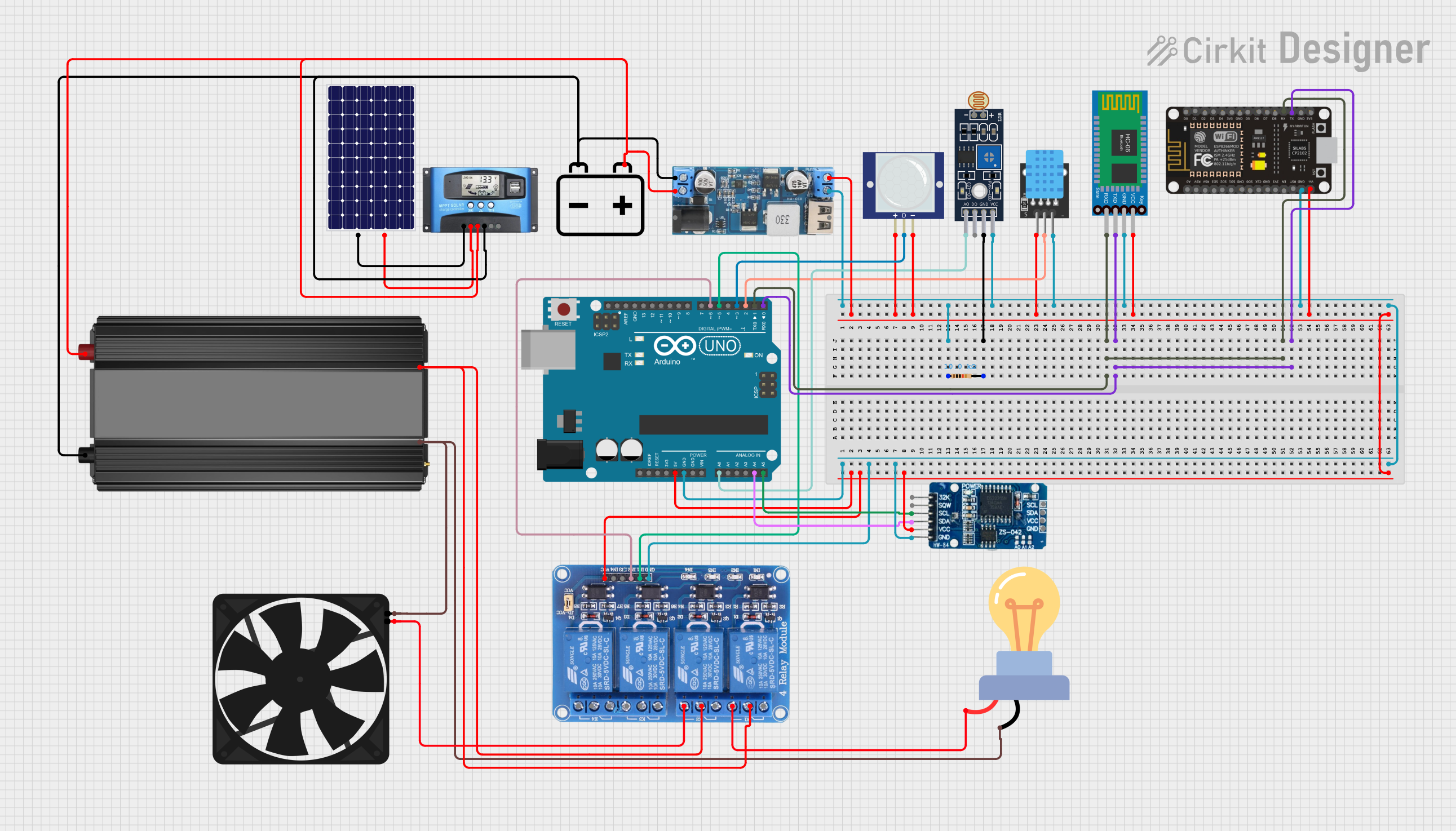
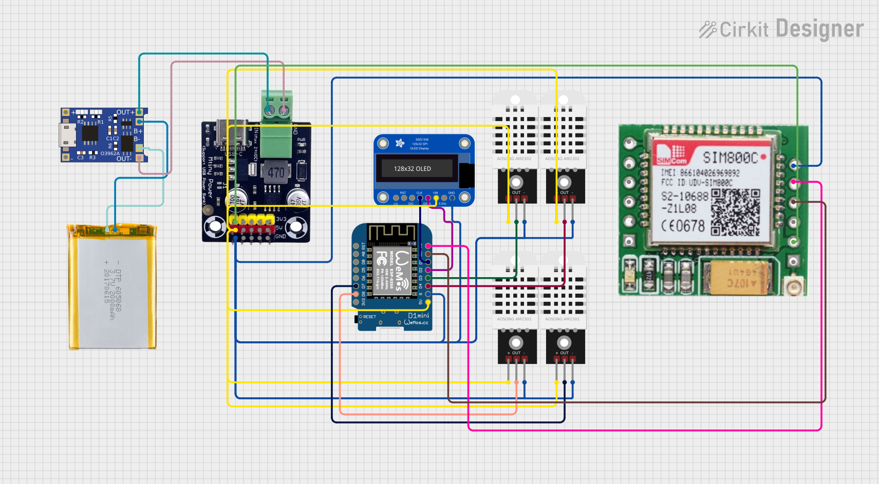

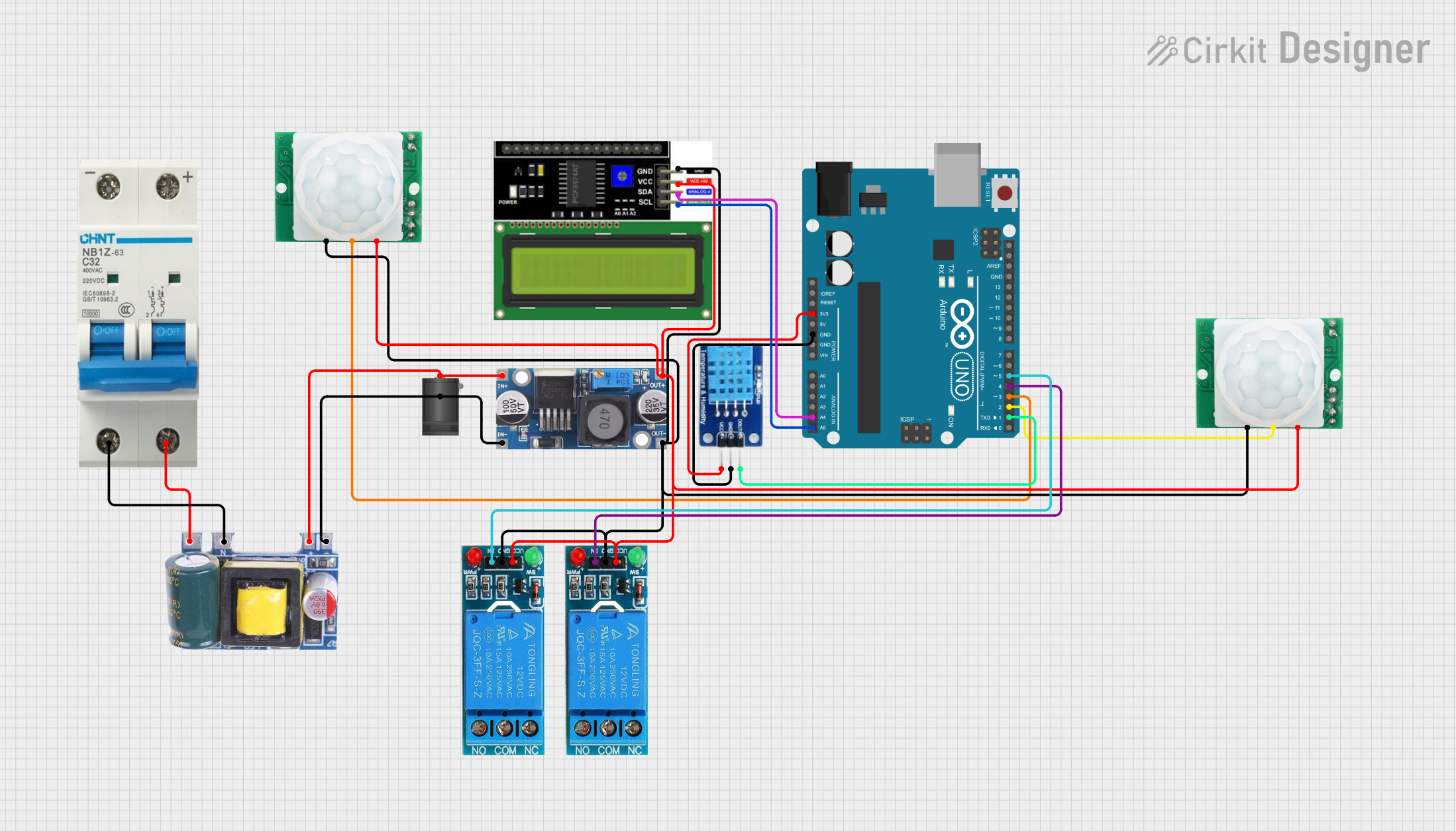
Explore Projects Built with ht12d
Common Applications
- Wireless remote controls for home automation
- Remote-controlled toys and vehicles
- Security systems and alarms
- Garage door openers
- Industrial remote control systems
Technical Specifications
The HT12D is a versatile decoder IC with the following key specifications:
| Parameter | Value |
|---|---|
| Operating Voltage | 2.4V to 12V |
| Operating Current | 0.4 mA (typical) |
| Maximum Oscillator Frequency | 50 kHz |
| Data Input | Serial data from RF receiver |
| Data Output | Parallel 4-bit data |
| Address Pins | 8 pins (A0 to A7) |
| Data Pins | 4 pins (D8 to D11) |
| Package Type | DIP-16 or SOP-16 |
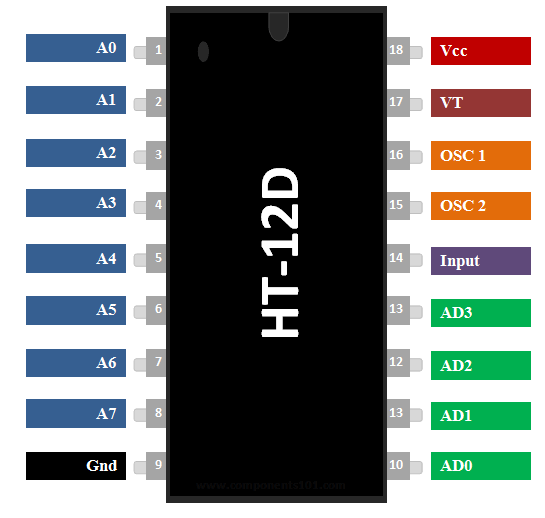
Pin Configuration and Descriptions
The HT12D has 16 pins, each with a specific function. The table below provides a detailed description of each pin:
| Pin Number | Pin Name | Description |
|---|---|---|
| 1-8 | A0-A7 | Address pins used to set the unique address of the device. |
| 9 | Ground (GND) | Ground pin for the IC. |
| 10 | Data In (DIN) | Serial data input pin, typically connected to the RF receiver module. |
| 11-14 | D8-D11 | Data output pins for decoded parallel data. |
| 15 | VT | Valid Transmission pin, goes HIGH when valid data is received. |
| 16 | VCC | Power supply pin (2.4V to 12V). |
Usage Instructions
How to Use the HT12D in a Circuit
- Power Supply: Connect the VCC pin (Pin 16) to a power source (2.4V to 12V) and the GND pin (Pin 9) to ground.
- Address Configuration: Set the address pins (A0 to A7) to a unique combination using pull-up or pull-down resistors. The same address must be configured on the corresponding HT12E encoder IC.
- Data Input: Connect the DIN pin (Pin 10) to the data output of an RF receiver module.
- Data Output: The decoded data will be available on the D8 to D11 pins (Pins 11 to 14). These pins can be connected to a microcontroller or other digital devices.
- Valid Transmission (VT): Monitor the VT pin (Pin 15). It will go HIGH when valid data is received.
Important Considerations
- Ensure that the address pins of the HT12D match the address pins of the HT12E encoder IC used in the transmitter.
- Use a 33 kΩ resistor between the oscillator pins of the HT12E and HT12D for proper operation.
- Keep the RF module and HT12D IC away from sources of electromagnetic interference to ensure reliable communication.
Example: Connecting HT12D to an Arduino UNO
Below is an example of how to interface the HT12D with an Arduino UNO to read decoded data:
// Example: Reading data from HT12D using Arduino UNO
// Connect HT12D D8-D11 pins to Arduino digital pins 2-5
// Connect VT pin to Arduino digital pin 6

#define D8_PIN 2  // HT12D D8 connected to Arduino pin 2
#define D9_PIN 3  // HT12D D9 connected to Arduino pin 3
#define D10_PIN 4 // HT12D D10 connected to Arduino pin 4
#define D11_PIN 5 // HT12D D11 connected to Arduino pin 5
#define VT_PIN 6  // HT12D VT connected to Arduino pin 6

void setup() {
  // Set data pins as input
  pinMode(D8_PIN, INPUT);
  pinMode(D9_PIN, INPUT);
  pinMode(D10_PIN, INPUT);
  pinMode(D11_PIN, INPUT);
  pinMode(VT_PIN, INPUT);

  // Start serial communication
  Serial.begin(9600);
}

void loop() {
  // Check if valid data is received
  if (digitalRead(VT_PIN) == HIGH) {
    // Read data from D8-D11
    int data = (digitalRead(D8_PIN) << 0) |
               (digitalRead(D9_PIN) << 1) |
               (digitalRead(D10_PIN) << 2) |
               (digitalRead(D11_PIN) << 3);

    // Print the received data
    Serial.print("Received Data: ");
    Serial.println(data, BIN); // Print data in binary format
  }
}
Troubleshooting and FAQs
Common Issues and Solutions
No Data Output on D8-D11 Pins:
- Ensure the address pins (A0 to A7) of the HT12D match the address pins of the HT12E encoder.
- Verify that the RF receiver module is properly connected to the DIN pin.
VT Pin Not Going HIGH:
- Check the power supply voltage and ensure it is within the operating range (2.4V to 12V).
- Confirm that the RF transmitter and receiver modules are operating on the same frequency.
Intermittent or Unreliable Communication:
- Use a decoupling capacitor (e.g., 0.1 µF) near the VCC and GND pins to reduce noise.
- Avoid placing the RF module and HT12D near high-frequency noise sources.
FAQs
Q: Can the HT12D be used with any RF module?
A: Yes, the HT12D can be used with most RF modules that support serial data transmission, such as 433 MHz or 315 MHz modules.
Q: What is the maximum range of communication?
A: The range depends on the RF module used. Typically, 433 MHz modules can achieve a range of 50-100 meters in open space.
Q: Can I use the HT12D without an encoder IC?
A: No, the HT12D requires encoded data from an HT12E or a compatible encoder IC to function correctly.