How to Use MAX9814: Examples, Pinouts, and Specs
Introduction
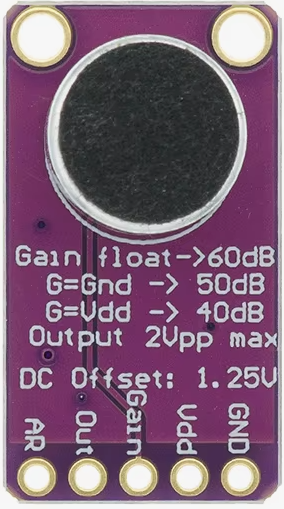
The MAX9814 is a low-noise microphone amplifier with Automatic Gain Control (AGC) designed to deliver high-quality audio amplification. Manufactured by Arduino, this component is ideal for applications requiring clear and consistent audio capture. Its AGC feature ensures optimal gain levels, making it suitable for environments with varying sound intensities. The MAX9814 is commonly used in voice recognition systems, portable audio devices, hearing aids, and other audio processing applications.
Explore Projects Built with MAX9814


Explore Projects Built with MAX9814
Technical Specifications
The MAX9814 is designed to provide excellent performance in audio applications. Below are its key technical specifications:
Key Specifications
- Supply Voltage (Vcc): 2.7V to 5.5V
- Quiescent Current: 3mA (typical)
- Input Impedance: 100kΩ
- Output Impedance: 200Ω
- Automatic Gain Control (AGC): Adjustable with external components
- Gain Settings: 40dB, 50dB, or 60dB (selectable via external resistor)
- Frequency Response: 20Hz to 20kHz
- Noise Figure: 2.5dB (typical)
- Operating Temperature Range: -40°C to +85°C
- Package Type: 8-pin SOIC or TDFN
Pin Configuration and Descriptions
The MAX9814 has an 8-pin configuration. Below is the pinout and description:
| Pin Number | Pin Name | Description |
|---|---|---|
| 1 | OUT | Amplifier output. Connect to the next stage of the audio circuit. |
| 2 | GND | Ground. Connect to the system ground. |
| 3 | BYPASS | Bypass capacitor connection for noise filtering. |
| 4 | VDD | Power supply input. Connect to a 2.7V to 5.5V power source. |
| 5 | GAIN | Gain control pin. Connect a resistor to set the desired gain level. |
| 6 | IN+ | Non-inverting microphone input. |
| 7 | IN- | Inverting microphone input. |
| 8 | SHDN | Shutdown pin. Pull low to disable the amplifier and reduce power consumption. |
Usage Instructions
The MAX9814 is straightforward to use in audio circuits. Below are the steps and considerations for integrating it into your design:
Basic Circuit Setup
Power Supply:
- Connect the VDD pin to a stable power source (2.7V to 5.5V).
- Connect the GND pin to the system ground.
Microphone Connection:
- Connect the microphone's positive terminal to the IN+ pin.
- Connect the microphone's negative terminal to the IN- pin.
Gain Configuration:
- Use an external resistor on the GAIN pin to set the desired gain level (40dB, 50dB, or 60dB).
Output Connection:
- Connect the OUT pin to the next stage of the audio circuit, such as an ADC or speaker driver.
Bypass Capacitor:
- Connect a capacitor (typically 1µF) between the BYPASS pin and ground to filter noise.
Shutdown Control:
- Pull the SHDN pin low to disable the amplifier when not in use, reducing power consumption.
Example Circuit with Arduino UNO
The MAX9814 can be interfaced with an Arduino UNO for audio signal processing. Below is an example setup:
Circuit Connections
- VDD: Connect to the 5V pin on the Arduino.
- GND: Connect to the GND pin on the Arduino.
- OUT: Connect to an analog input pin (e.g., A0) on the Arduino.
- SHDN: Connect to a digital pin (e.g., D2) for shutdown control.
- GAIN: Connect a resistor to set the gain (e.g., 10kΩ for 50dB).
- BYPASS: Connect a 1µF capacitor to ground.
- IN+ and IN-: Connect to the microphone terminals.
Example Arduino Code
// MAX9814 Example Code for Arduino UNO
// This code reads the audio signal from the MAX9814 and outputs the
// analog value to the Serial Monitor.

const int audioInputPin = A0; // Analog pin connected to MAX9814 OUT
const int shutdownPin = 2;   // Digital pin connected to MAX9814 SHDN

void setup() {
  pinMode(shutdownPin, OUTPUT); // Set SHDN pin as output
  digitalWrite(shutdownPin, HIGH); // Enable the MAX9814
  Serial.begin(9600); // Initialize Serial communication
}

void loop() {
  int audioSignal = analogRead(audioInputPin); // Read audio signal
  Serial.println(audioSignal); // Print the signal value to Serial Monitor
  delay(10); // Small delay for stability
}
Best Practices
- Use decoupling capacitors near the VDD pin to ensure stable operation.
- Keep the microphone and input traces as short as possible to minimize noise.
- Shield the circuit from external electromagnetic interference (EMI) for optimal performance.
Troubleshooting and FAQs
Common Issues and Solutions
No Output Signal:
- Ensure the SHDN pin is pulled high to enable the amplifier.
- Verify the power supply voltage is within the specified range (2.7V to 5.5V).
- Check all connections, especially the microphone and output connections.
Distorted Audio:
- Verify the gain resistor value is appropriate for your application.
- Ensure the input signal is not exceeding the amplifier's input range.
Excessive Noise:
- Add a bypass capacitor (1µF) to the BYPASS pin for noise filtering.
- Check for proper grounding and minimize the length of input traces.
High Power Consumption:
- Use the SHDN pin to disable the amplifier when not in use.
FAQs
Q: Can the MAX9814 work with a 3.3V power supply?
A: Yes, the MAX9814 operates with a supply voltage range of 2.7V to 5.5V, making it compatible with 3.3V systems.
Q: How do I adjust the AGC settings?
A: The AGC settings can be adjusted by selecting appropriate external components as specified in the MAX9814 datasheet.
Q: Can I use the MAX9814 with a digital microphone?
A: No, the MAX9814 is designed for use with analog microphones. Digital microphones require a different interface.
Q: What is the maximum gain of the MAX9814?
A: The maximum gain is 60dB, which can be set using an external resistor on the GAIN pin.
By following this documentation, you can effectively integrate the MAX9814 into your audio projects for high-quality sound amplification.