Cirkit Designer
Your all-in-one circuit design IDE
Home /
Component Documentation
How to Use MiCS-2714: Examples, Pinouts, and Specs
Introduction
The MiCS-2714 is a gas sensor designed for detecting nitrogen dioxide (NO2) in the air. It is widely used in air quality monitoring systems and environmental sensing applications. This sensor provides reliable and accurate measurements, making it an essential component for projects that require monitoring of NO2 levels.
Explore Projects Built with MiCS-2714
Lilygo 7670e-Based Smart Interface with LCD Display and Keypad

This circuit features a Lilygo 7670e microcontroller interfaced with a 16x2 I2C LCD for display, a 4X4 membrane matrix keypad for input, and an arcade button for additional control. It also includes a 4G antenna and a GPS antenna for communication and location tracking capabilities.
ESP32-Based Audio Recorder and Playback System with Servo Control and LED Indicators
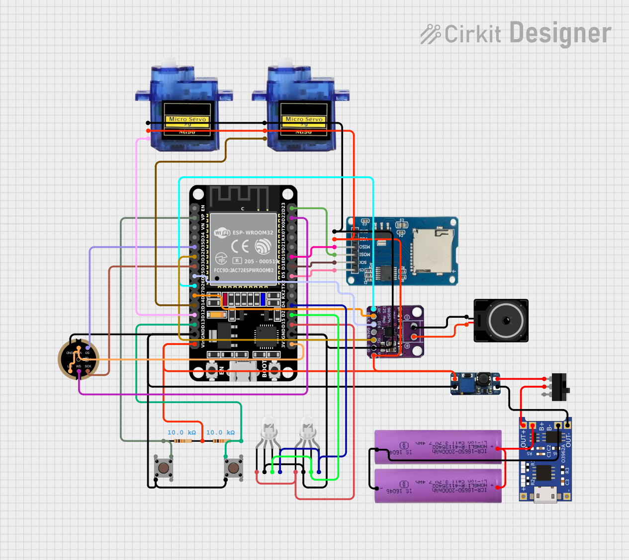
This circuit is a versatile embedded system featuring an ESP32 microcontroller for processing audio signals, controlling servos, and managing data storage. It includes audio input and output capabilities, visual indicators, and user interface elements, all powered by a rechargeable Li-ion battery with charging and voltage regulation.
ESP8266 and SIM800L Based GPS Tracker with I2C LCD Display and Battery Power

This circuit integrates an ESP8266 NodeMCU microcontroller with a SIM800L GSM module, a GPS NEO 6M module, and a 16x2 I2C LCD display for communication and location tracking. It also includes a pushbutton for user input, a piezo buzzer for audio alerts, and is powered by a 2x 18650 battery pack through an LM2596 step-down module.
ESP32-Based GPS Tracker with Bluetooth Connectivity and Camera Interface
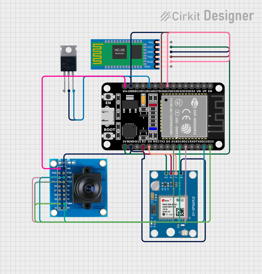
This circuit features an ESP32 microcontroller interfaced with a Neo 6M GPS Module, an OV7725 camera module, an HC-05 Bluetooth Module, and a BT139 600 triac. The ESP32 is programmed to read GPS data from the Neo 6M module and likely transmit it via Bluetooth using the HC-05 module. The OV7725 camera module is connected to the ESP32 for image capture, and the BT139 600 triac is interfaced for controlling power to an unspecified load.
Explore Projects Built with MiCS-2714
Lilygo 7670e-Based Smart Interface with LCD Display and Keypad
This circuit features a Lilygo 7670e microcontroller interfaced with a 16x2 I2C LCD for display, a 4X4 membrane matrix keypad for input, and an arcade button for additional control. It also includes a 4G antenna and a GPS antenna for communication and location tracking capabilities.
ESP32-Based Audio Recorder and Playback System with Servo Control and LED Indicators
This circuit is a versatile embedded system featuring an ESP32 microcontroller for processing audio signals, controlling servos, and managing data storage. It includes audio input and output capabilities, visual indicators, and user interface elements, all powered by a rechargeable Li-ion battery with charging and voltage regulation.
ESP8266 and SIM800L Based GPS Tracker with I2C LCD Display and Battery Power
This circuit integrates an ESP8266 NodeMCU microcontroller with a SIM800L GSM module, a GPS NEO 6M module, and a 16x2 I2C LCD display for communication and location tracking. It also includes a pushbutton for user input, a piezo buzzer for audio alerts, and is powered by a 2x 18650 battery pack through an LM2596 step-down module.
ESP32-Based GPS Tracker with Bluetooth Connectivity and Camera Interface
This circuit features an ESP32 microcontroller interfaced with a Neo 6M GPS Module, an OV7725 camera module, an HC-05 Bluetooth Module, and a BT139 600 triac. The ESP32 is programmed to read GPS data from the Neo 6M module and likely transmit it via Bluetooth using the HC-05 module. The OV7725 camera module is connected to the ESP32 for image capture, and the BT139 600 triac is interfaced for controlling power to an unspecified load.
Technical Specifications
Key Technical Details
| Parameter | Value |
|---|---|
| Operating Voltage | 5V DC |
| Power Consumption | < 60 mW |
| Detection Range | 0.05 - 5 ppm NO2 |
| Sensitivity | 0.1 - 0.5 mV/ppm |
| Response Time | < 60 seconds |
| Operating Temperature | -30°C to +50°C |
| Humidity Range | 5% - 95% RH (non-condensing) |
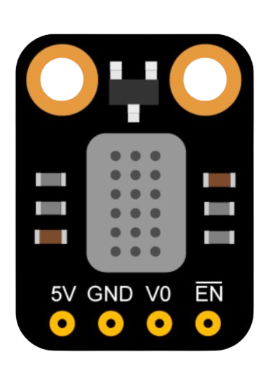
Pin Configuration and Descriptions
| Pin Number | Pin Name | Description |
|---|---|---|
| 1 | VCC | Power supply (5V) |
| 2 | GND | Ground |
| 3 | VOUT | Analog output voltage proportional to NO2 concentration |
| 4 | NC | Not connected |
Usage Instructions
How to Use the MiCS-2714 in a Circuit
- Power Supply: Connect the VCC pin to a 5V power supply and the GND pin to the ground.
- Analog Output: Connect the VOUT pin to an analog input pin on your microcontroller (e.g., Arduino UNO).
- Read Data: Use the analogRead() function to read the voltage from the VOUT pin, which corresponds to the NO2 concentration.
Important Considerations and Best Practices
- Calibration: Ensure the sensor is properly calibrated for accurate readings.
- Placement: Place the sensor in an area with good airflow to get representative air quality measurements.
- Warm-Up Time: Allow the sensor to warm up for a few minutes before taking readings to ensure stability.
- Avoid Contaminants: Keep the sensor away from contaminants and high humidity to prevent damage.
Example Code for Arduino UNO
// MiCS-2714 Gas Sensor Example Code
// This code reads the analog output from the MiCS-2714 sensor and prints
// the NO2 concentration to the Serial Monitor.

const int sensorPin = A0; // Analog input pin connected to VOUT of MiCS-2714

void setup() {
  Serial.begin(9600); // Initialize serial communication at 9600 baud rate
}

void loop() {
  int sensorValue = analogRead(sensorPin); // Read the analog value from the sensor
  float voltage = sensorValue * (5.0 / 1023.0); // Convert the analog value to voltage
  float no2Concentration = voltageToConcentration(voltage); // Convert voltage to NO2 concentration

  Serial.print("NO2 Concentration: ");
  Serial.print(no2Concentration);
  Serial.println(" ppm");

  delay(1000); // Wait for 1 second before taking another reading
}

// Function to convert voltage to NO2 concentration
float voltageToConcentration(float voltage) {
  // Assuming a linear relationship between voltage and NO2 concentration
  // Adjust the formula based on the sensor's datasheet and calibration
  return voltage * 10.0; // Example conversion factor
}
Troubleshooting and FAQs
Common Issues and Solutions
No Output or Incorrect Readings:
- Solution: Check the power connections and ensure the sensor is properly connected to the microcontroller. Verify that the sensor has warmed up.
Fluctuating Readings:
- Solution: Ensure the sensor is placed in a stable environment with consistent airflow. Avoid placing the sensor near sources of interference.
Slow Response Time:
- Solution: Allow the sensor to warm up for a longer period before taking readings. Ensure the sensor is not exposed to extreme temperatures or humidity.
FAQs
Q1: How do I calibrate the MiCS-2714 sensor?
- A1: Calibration involves exposing the sensor to known concentrations of NO2 and adjusting the output readings accordingly. Refer to the sensor's datasheet for detailed calibration procedures.
Q2: Can the MiCS-2714 detect other gases?
- A2: The MiCS-2714 is specifically designed for NO2 detection. While it may respond to other gases, its sensitivity and accuracy are optimized for NO2.
Q3: What is the lifespan of the MiCS-2714 sensor?
- A3: The sensor's lifespan depends on operating conditions. Under normal conditions, it can last several years. Regular calibration and proper maintenance can extend its lifespan.
By following this documentation, users can effectively integrate the MiCS-2714 gas sensor into their projects, ensuring accurate and reliable NO2 detection.