
How to Use L3GD20H Triple-Axis Gyro Breakout Board: Examples, Pinouts, and Specs
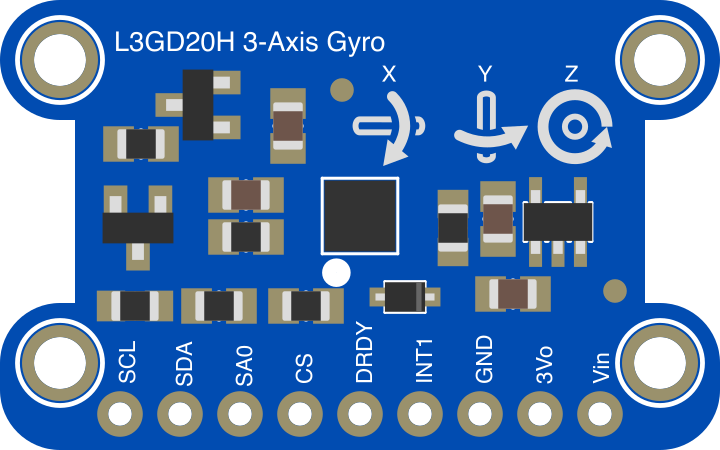
 Design with L3GD20H Triple-Axis Gyro Breakout Board in Cirkit Designer
Introduction
The L3GD20H Triple-Axis Gyro Breakout Board (Manufacturer Part ID: 1032) by Adafruit is a compact and high-performance sensor module designed to measure angular velocity across three axes (X, Y, and Z). This breakout board is based on the L3GD20H gyroscope sensor, which provides precise motion tracking capabilities. It is ideal for applications such as robotics, drones, gaming controllers, and other motion-sensing projects.
This module is equipped with a user-friendly breakout board design, making it easy to integrate into various projects. It communicates via I2C or SPI, offering flexibility for different microcontroller platforms.
Explore Projects Built with L3GD20H Triple-Axis Gyro Breakout Board
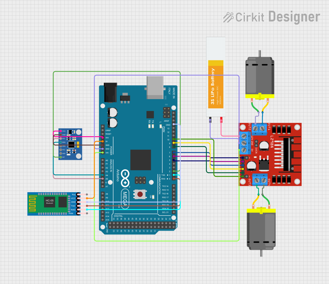 Open Project in Cirkit Designer
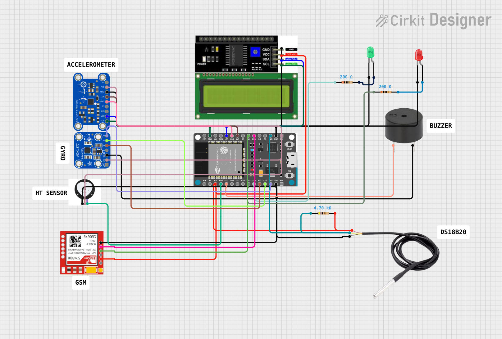 Open Project in Cirkit Designer
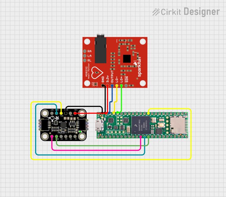 Open Project in Cirkit Designer
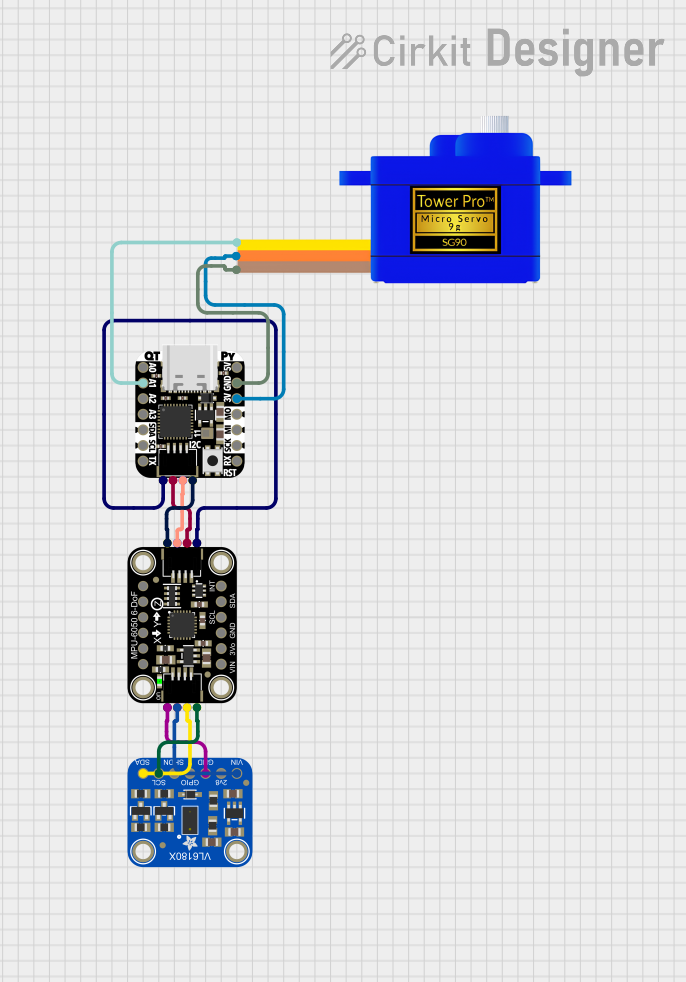 Open Project in Cirkit Designer
Explore Projects Built with L3GD20H Triple-Axis Gyro Breakout Board
Open Project in Cirkit DesignerOpen Project in Cirkit DesignerOpen Project in Cirkit DesignerOpen Project in Cirkit DesignerTechnical Specifications
Key Technical Details
- Sensor: L3GD20H gyroscope
- Measurement Range: ±245, ±500, ±2000 degrees per second (selectable)
- Communication Interfaces: I2C (up to 400 kHz) and SPI (up to 10 MHz)
- Supply Voltage: 3.3V (logic level) or 5V (via onboard regulator)
- Current Consumption: 6.1 mA (typical)
- Operating Temperature Range: -40°C to +85°C
- Dimensions: 20mm x 20mm x 3mm
- Weight: ~1g
Pin Configuration and Descriptions
The breakout board has 8 pins, as described in the table below:
| Pin Name | Description |
|---|---|
| VIN | Power input (3.3V to 5V). Powers the onboard voltage regulator. |
| GND | Ground connection. |
| SDA | I2C data line. Connect to the microcontroller's SDA pin. |
| SCL | I2C clock line. Connect to the microcontroller's SCL pin. |
| SDO | SPI/I2C address selection or SPI MISO (Master In Slave Out). |
| CS | SPI chip select. Pull low to enable SPI communication. |
| SCLK | SPI clock line. |
| SDI | SPI MOSI (Master Out Slave In). |
Usage Instructions
How to Use the Component in a Circuit
- Powering the Board: Connect the VIN pin to a 3.3V or 5V power source and GND to ground.
- Choosing Communication Protocol:
- For I2C: Connect the SDA and SCL pins to the corresponding pins on your microcontroller. Use the SDO pin to set the I2C address (low for
0x6A, high for0x6B). - For SPI: Connect the CS, SCLK, SDI, and SDO pins to the respective SPI pins on your microcontroller.
- For I2C: Connect the SDA and SCL pins to the corresponding pins on your microcontroller. Use the SDO pin to set the I2C address (low for
- Pull-Up Resistors: If using I2C, ensure pull-up resistors (typically 4.7kΩ) are present on the SDA and SCL lines.
- Bypass Capacitor: Place a 0.1µF capacitor between VIN and GND for noise filtering.
Important Considerations and Best Practices
- Voltage Levels: Ensure your microcontroller's logic levels match the breakout board's requirements (3.3V or 5V).
- Mounting: Secure the breakout board to minimize vibrations, which can affect readings.
- Calibration: Perform sensor calibration to account for offsets and improve accuracy.
- Data Filtering: Use software filtering (e.g., moving average) to smooth out noisy data.
Example Code for Arduino UNO (I2C)
Below is an example of how to interface the L3GD20H with an Arduino UNO using I2C:
#include <Wire.h>

// L3GD20H I2C address (default: 0x6B if SDO is high, 0x6A if SDO is low)
#define L3GD20H_ADDRESS 0x6B

// Register addresses
#define CTRL_REG1 0x20
#define OUT_X_L  0x28

void setup() {
  Wire.begin(); // Initialize I2C communication
  Serial.begin(9600); // Initialize serial communication for debugging

  // Configure the L3GD20H
  Wire.beginTransmission(L3GD20H_ADDRESS);
  Wire.write(CTRL_REG1); // Access CTRL_REG1
  Wire.write(0x0F); // Enable X, Y, Z axes and set power mode
  Wire.endTransmission();

  Serial.println("L3GD20H initialized!");
}

void loop() {
  int16_t gyroX, gyroY, gyroZ;

  // Read X-axis angular velocity
  gyroX = readGyro(OUT_X_L);
  // Read Y-axis angular velocity
  gyroY = readGyro(OUT_X_L + 2);
  // Read Z-axis angular velocity
  gyroZ = readGyro(OUT_X_L + 4);

  // Print the angular velocity values
  Serial.print("X: "); Serial.print(gyroX);
  Serial.print(" Y: "); Serial.print(gyroY);
  Serial.print(" Z: "); Serial.println(gyroZ);

  delay(100); // Delay for readability
}

// Function to read 16-bit gyro data from a register
int16_t readGyro(uint8_t reg) {
  Wire.beginTransmission(L3GD20H_ADDRESS);
  Wire.write(reg | 0x80); // Set MSB for auto-increment
  Wire.endTransmission();
  Wire.requestFrom(L3GD20H_ADDRESS, 2);

  if (Wire.available() == 2) {
    uint8_t lsb = Wire.read();
    uint8_t msb = Wire.read();
    return (int16_t)(msb << 8 | lsb);
  }
  return 0; // Return 0 if no data is available
}
Troubleshooting and FAQs
Common Issues and Solutions
No Data Output:
- Ensure the breakout board is powered correctly (check VIN and GND connections).
- Verify the I2C or SPI connections and ensure the correct protocol is selected.
- Check the I2C address or SPI configuration in your code.
Incorrect or Noisy Readings:
- Ensure the breakout board is securely mounted to reduce vibrations.
- Perform sensor calibration to eliminate offsets.
- Use software filtering to smooth out noisy data.
Communication Errors:
- Double-check the pull-up resistors on the I2C lines.
- Verify that the microcontroller's logic levels are compatible with the breakout board.
FAQs
Q: Can I use this breakout board with a 5V microcontroller?
A: Yes, the onboard voltage regulator allows the board to work with 5V systems. However, ensure the logic levels are compatible.
Q: How do I change the I2C address?
A: Use the SDO pin to set the I2C address. Connect it to GND for 0x6A or to VIN for 0x6B.
Q: What is the maximum sampling rate of the L3GD20H?
A: The L3GD20H supports a maximum output data rate of 800 Hz.
Q: Can I use this board for tilt sensing?
A: While the L3GD20H measures angular velocity, it does not directly measure tilt. For tilt sensing, consider combining it with an accelerometer.