How to Use SGP40: Examples, Pinouts, and Specs
Introduction
The SGP40, manufactured by DFRobot, is a digital gas sensor designed for indoor air quality monitoring. It is capable of detecting a wide range of volatile organic compounds (VOCs) and provides a digital signal output, making it easy to integrate into various applications. The sensor is ideal for use in air purifiers, HVAC systems, and other devices that monitor or improve indoor air quality. Its compact design and robust performance make it a popular choice for both hobbyists and professionals.
Explore Projects Built with SGP40


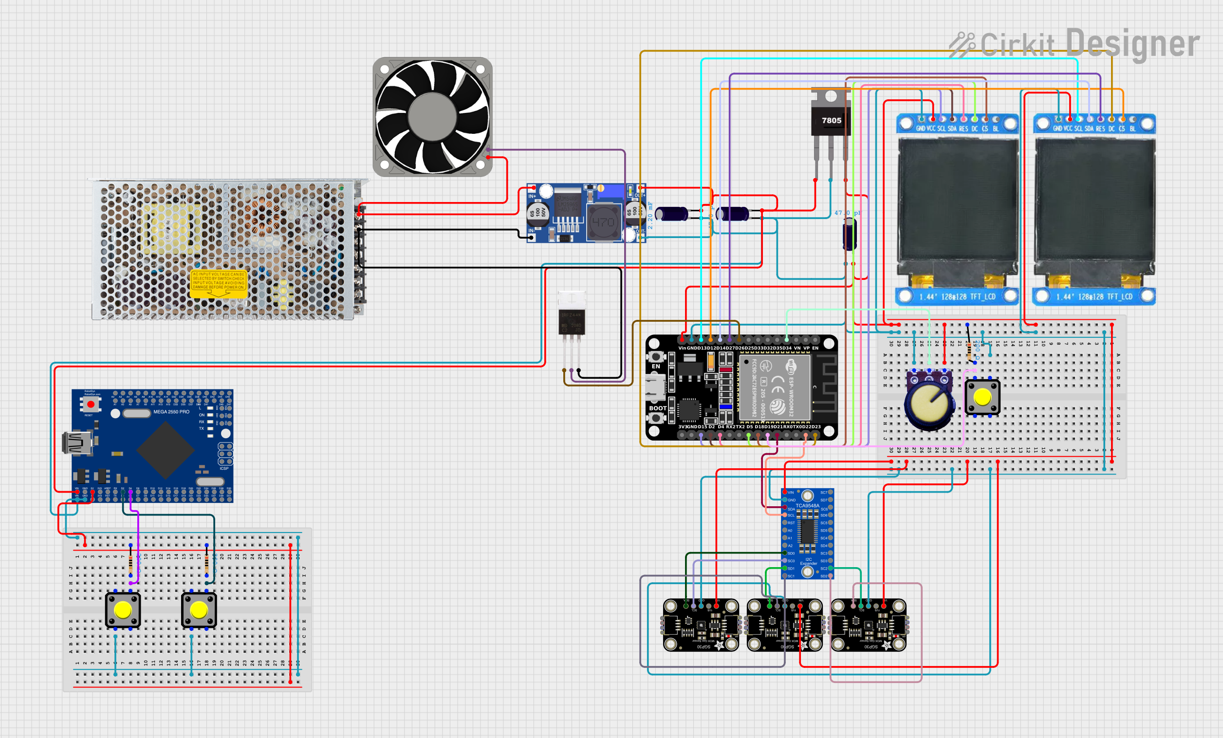

Explore Projects Built with SGP40
Common Applications
- Indoor air quality monitoring
- Air purifiers and ventilation systems
- Smart home devices
- Environmental monitoring systems
- IoT-based air quality solutions
Technical Specifications
Below are the key technical details of the SGP40 sensor:
| Parameter | Value |
|---|---|
| Supply Voltage | 1.8V to 3.6V |
| Interface | I²C |
| Operating Temperature | -10°C to +50°C |
| Humidity Range | 0% to 90% RH (non-condensing) |
| Power Consumption | 2.6 mA (typical) |
| Measurement Range | 0 to 1,000 ppm (VOC Index) |
| Output | Digital (VOC Index) |
| Dimensions | 2.44 mm × 2.44 mm × 0.85 mm |
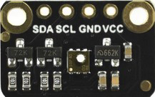
Pin Configuration
The SGP40 sensor has a simple pinout for easy integration. Below is the pin configuration:
| Pin Name | Description |
|---|---|
| VDD | Power supply (1.8V to 3.6V) |
| GND | Ground |
| SDA | I²C data line |
| SCL | I²C clock line |
| ADDR | I²C address selection (connect to GND or VDD) |
Usage Instructions
Connecting the SGP40 to a Microcontroller
To use the SGP40, connect it to a microcontroller such as an Arduino UNO via the I²C interface. Below is a typical wiring setup:
- Connect the VDD pin to the 3.3V output of the Arduino.
- Connect the GND pin to the ground (GND) of the Arduino.
- Connect the SDA pin to the Arduino's A4 pin (I²C data line).
- Connect the SCL pin to the Arduino's A5 pin (I²C clock line).
Important Considerations
- Power Supply: Ensure the sensor operates within the specified voltage range (1.8V to 3.6V). Using a voltage regulator may be necessary if your microcontroller operates at 5V.
- I²C Pull-Up Resistors: The I²C lines (SDA and SCL) require pull-up resistors (typically 4.7kΩ). Some breakout boards include these resistors; check the datasheet or board documentation.
- Environmental Conditions: Avoid exposing the sensor to extreme humidity or temperatures outside its operating range, as this may affect accuracy or damage the sensor.
Sample Arduino Code
Below is an example of how to interface the SGP40 with an Arduino UNO to read VOC data:
#include <Wire.h>

// I2C address of the SGP40 sensor
#define SGP40_ADDRESS 0x59

void setup() {
  Wire.begin(); // Initialize I2C communication
  Serial.begin(9600); // Start serial communication for debugging

  // Initialize the sensor
  Serial.println("Initializing SGP40...");
  if (!initializeSGP40()) {
    Serial.println("Failed to initialize SGP40. Check connections.");
    while (1); // Halt execution if initialization fails
  }
  Serial.println("SGP40 initialized successfully.");
}

void loop() {
  uint16_t vocIndex = readVOCIndex(); // Read VOC index from the sensor
  Serial.print("VOC Index: ");
  Serial.println(vocIndex); // Print the VOC index to the serial monitor
  delay(1000); // Wait 1 second before the next reading
}

// Function to initialize the SGP40 sensor
bool initializeSGP40() {
  Wire.beginTransmission(SGP40_ADDRESS);
  // Send a dummy command to check if the sensor responds
  Wire.write(0x20); // Example command (refer to the datasheet for actual commands)
  Wire.write(0x08);
  return (Wire.endTransmission() == 0); // Return true if the sensor responds
}

// Function to read VOC index from the SGP40 sensor
uint16_t readVOCIndex() {
  Wire.beginTransmission(SGP40_ADDRESS);
  Wire.write(0x26); // Example command to read VOC index
  Wire.write(0x0F);
  Wire.endTransmission();

  delay(10); // Wait for the sensor to process the command

  Wire.requestFrom(SGP40_ADDRESS, 2); // Request 2 bytes of data
  if (Wire.available() == 2) {
    uint8_t msb = Wire.read(); // Most significant byte
    uint8_t lsb = Wire.read(); // Least significant byte
    return (msb << 8) | lsb; // Combine bytes into a 16-bit value
  }
  return 0; // Return 0 if no data is available
}
Notes on the Code
- Replace the example I²C commands (
0x20,0x08,0x26,0x0F) with the actual commands from the SGP40 datasheet. - Ensure the I²C address (
0x59) matches the sensor's default or configured address.
Troubleshooting and FAQs
Common Issues
No Response from the Sensor
- Cause: Incorrect wiring or I²C address mismatch.
- Solution: Double-check the wiring and ensure the I²C address matches the sensor's configuration.
Inaccurate Readings
- Cause: Environmental factors such as high humidity or temperature.
- Solution: Ensure the sensor operates within its specified environmental range.
I²C Communication Errors
- Cause: Missing or incorrect pull-up resistors on the I²C lines.
- Solution: Add 4.7kΩ pull-up resistors to the SDA and SCL lines if not already present.
FAQs
Can the SGP40 detect specific gases?
- The SGP40 is designed to detect a broad range of VOCs but does not differentiate between specific gases.
What is the VOC Index?
- The VOC Index is a normalized value representing the concentration of VOCs in the air. It is not a direct measurement of ppm but provides a relative indication of air quality.
Can I use the SGP40 with a 5V microcontroller?
- Yes, but you must use a level shifter or voltage regulator to ensure the sensor operates within its 1.8V to 3.6V range.
By following this documentation, you can successfully integrate the SGP40 into your projects and monitor indoor air quality with ease.