
How to Use Adafruit ATtinyx16 Breakout: Examples, Pinouts, and Specs
 Design with Adafruit ATtinyx16 Breakout in Cirkit Designer
Introduction
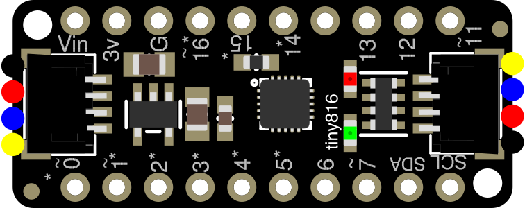
The Adafruit ATtinyx16 Breakout (Manufacturer Part ID: 5690) is a compact and versatile breakout board designed for the ATtinyx16 microcontroller series. This breakout board simplifies prototyping and integration by providing easy access to all the microcontroller's pins, along with power and ground connections. Its small form factor makes it ideal for embedded applications where space is a constraint.
Explore Projects Built with Adafruit ATtinyx16 Breakout
 Open Project in Cirkit Designer
 Open Project in Cirkit Designer
 Open Project in Cirkit Designer
 Open Project in Cirkit Designer
Explore Projects Built with Adafruit ATtinyx16 Breakout
Open Project in Cirkit DesignerOpen Project in Cirkit DesignerOpen Project in Cirkit DesignerOpen Project in Cirkit DesignerCommon Applications and Use Cases
- IoT devices and low-power embedded systems
- Sensor interfacing and data acquisition
- Small-scale robotics and automation
- Wearable electronics
- Educational projects and prototyping
Technical Specifications
The Adafruit ATtinyx16 Breakout is built around the ATtinyx16 microcontroller, which is part of the AVR family. Below are the key technical details:
Microcontroller Specifications
| Parameter | Value |
|---|---|
| Microcontroller | ATtinyx16 (ATtiny416/816/1616) |
| Operating Voltage | 1.8V to 5.5V |
| Flash Memory | 16 KB |
| SRAM | 2 KB |
| EEPROM | 256 Bytes |
| Clock Speed | Up to 20 MHz |
| GPIO Pins | 18 |
| ADC Channels | 12-bit ADC, up to 10 channels |
| Communication Interfaces | I2C, SPI, UART |
| PWM Channels | Up to 6 |
Pin Configuration and Descriptions
The breakout board provides access to all the pins of the ATtinyx16 microcontroller. Below is the pinout description:
| Pin Name | Pin Number | Description |
|---|---|---|
| VCC | 1 | Power supply (1.8V to 5.5V) |
| GND | 2 | Ground |
| PA0-PA7 | 3-10 | General-purpose I/O pins |
| PB0-PB7 | 11-18 | General-purpose I/O pins |
| PC0-PC2 | 19-21 | General-purpose I/O pins |
| RESET | 22 | Reset pin |
| UPDI | 23 | Unified Program and Debug Interface |
| XTAL1 | 24 | External clock input |
| XTAL2 | 25 | External clock output |
Usage Instructions
How to Use the Component in a Circuit
- Powering the Board: Connect the VCC pin to a power source (1.8V to 5.5V) and the GND pin to ground.
- Programming the Microcontroller: Use the UPDI pin for programming and debugging. A UPDI programmer (e.g., USB-to-UPDI adapter) is required.
- Connecting Peripherals: Use the GPIO pins (PAx, PBx, PCx) to interface with sensors, actuators, or other peripherals. Configure the pins as input or output in your code.
- Clock Configuration: The ATtinyx16 can operate with an internal oscillator or an external crystal. Connect an external crystal to the XTAL1 and XTAL2 pins if required.
Important Considerations and Best Practices
- Ensure the power supply voltage matches the operating voltage range of the ATtinyx16 (1.8V to 5.5V).
- Use decoupling capacitors (e.g., 0.1 µF) near the VCC and GND pins to stabilize the power supply.
- Avoid leaving unused pins floating; configure them as inputs with pull-up resistors or as outputs.
- When using the UPDI pin for programming, ensure it is not connected to other components during the programming process.
Example Code for Arduino UNO
The ATtinyx16 can be programmed using the Arduino IDE with the appropriate core installed. Below is an example of blinking an LED connected to pin PA0:
// Example: Blink an LED connected to PA0 on the ATtinyx16

// Define the pin number for the LED
#define LED_PIN 0 // PA0 corresponds to digital pin 0 in Arduino IDE

void setup() {
  pinMode(LED_PIN, OUTPUT); // Set PA0 as an output pin
}

void loop() {
  digitalWrite(LED_PIN, HIGH); // Turn the LED on
  delay(1000);                 // Wait for 1 second
  digitalWrite(LED_PIN, LOW);  // Turn the LED off
  delay(1000);                 // Wait for 1 second
}
Note: To program the ATtinyx16 using the Arduino IDE, install the "megaTinyCore" library and select the appropriate board and programmer settings.
Troubleshooting and FAQs
Common Issues and Solutions
Microcontroller Not Responding
- Cause: Incorrect power supply voltage.
- Solution: Verify that the VCC pin is supplied with a voltage within the 1.8V to 5.5V range.
Unable to Program the Microcontroller
- Cause: UPDI pin not properly connected or incorrect programmer settings.
- Solution: Ensure the UPDI pin is connected to a compatible programmer and verify the settings in the programming software.
Peripheral Devices Not Working
- Cause: Incorrect pin configuration or wiring.
- Solution: Double-check the pin configuration in your code and ensure proper wiring.
Unstable Operation
- Cause: Insufficient decoupling capacitors.
- Solution: Add a 0.1 µF capacitor near the VCC and GND pins.
FAQs
Q: Can I use the ATtinyx16 with a 3.3V power supply?
A: Yes, the ATtinyx16 operates within a voltage range of 1.8V to 5.5V, so 3.3V is within the acceptable range.
Q: How do I reset the microcontroller?
A: Connect the RESET pin to ground momentarily to reset the microcontroller.
Q: Can I use the UPDI pin as a GPIO?
A: Yes, the UPDI pin can be configured as a GPIO pin, but it is recommended to reserve it for programming and debugging purposes.
Q: Is an external crystal required?
A: No, the ATtinyx16 has an internal oscillator. However, you can use an external crystal for higher precision if needed.