How to Use SCD41: Examples, Pinouts, and Specs
Introduction
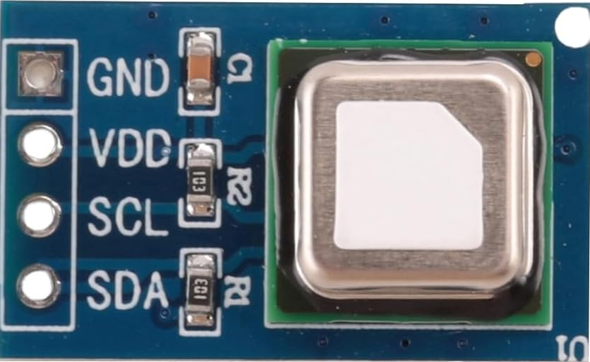
The SCD41 is a digital sensor designed for measuring carbon dioxide (CO2), temperature, and humidity. Manufactured by Adafruit, it employs non-dispersive infrared (NDIR) technology for CO2 detection, ensuring high accuracy and reliability. This compact sensor is ideal for applications requiring precise indoor air quality monitoring, such as HVAC systems, air purifiers, smart home devices, and environmental monitoring systems.
Explore Projects Built with SCD41

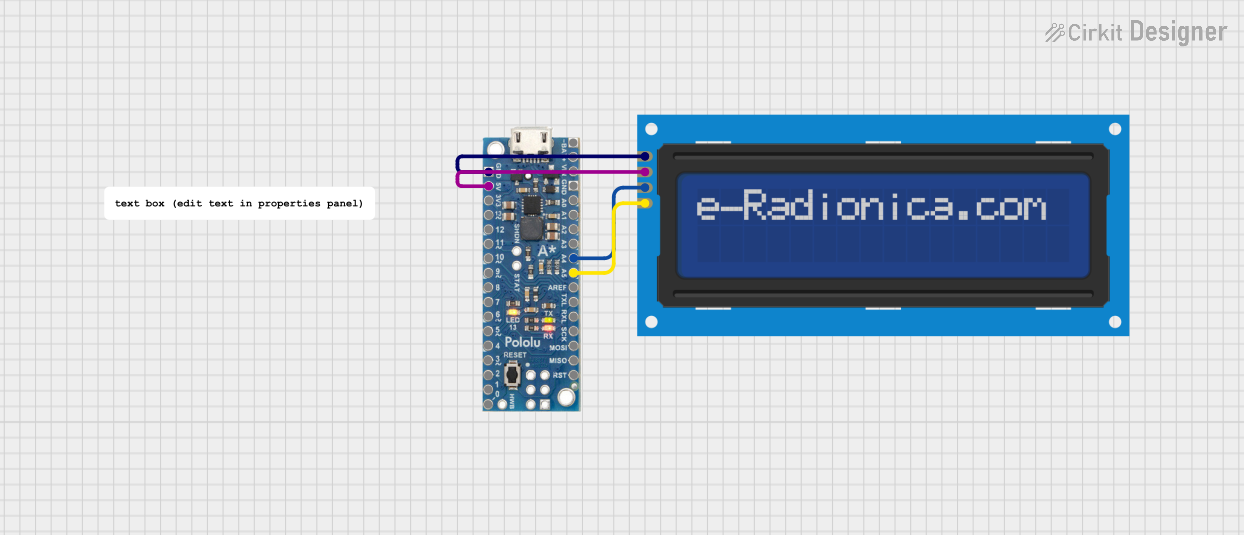
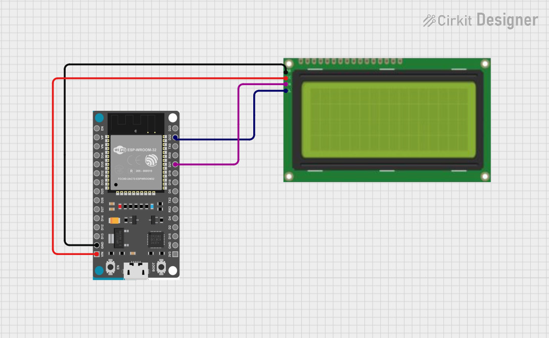

Explore Projects Built with SCD41
Common Applications
- Indoor air quality monitoring
- HVAC systems
- Smart home automation
- Air purifiers and ventilation systems
- Environmental data logging
Technical Specifications
The SCD41 sensor offers robust performance with the following key specifications:
| Parameter | Value |
|---|---|
| CO2 Measurement Range | 400 ppm to 5000 ppm |
| CO2 Accuracy | ±(40 ppm + 5% of reading) |
| Temperature Range | -10°C to 60°C |
| Temperature Accuracy | ±0.8°C |
| Humidity Range | 0% to 100% RH |
| Humidity Accuracy | ±5% RH |
| Supply Voltage | 2.4V to 5.5V |
| Interface | I²C (default address: 0x62) |
| Power Consumption | 1.7 mA (idle) / 24 mA (measurement) |
| Dimensions | 10.1 mm x 10.1 mm x 6.5 mm |
Pin Configuration
The SCD41 sensor has a simple pinout for easy integration into circuits:
| Pin | Name | Description |
|---|---|---|
| 1 | VDD | Power supply (2.4V to 5.5V) |
| 2 | GND | Ground |
| 3 | SDA | I²C data line |
| 4 | SCL | I²C clock line |
| 5 | SEL | Address select (connect to GND for default address) |
| 6 | NC | Not connected (leave unconnected) |
Usage Instructions
How to Use the SCD41 in a Circuit
- Power the Sensor: Connect the VDD pin to a 3.3V or 5V power source and the GND pin to ground.
- I²C Communication: Connect the SDA and SCL pins to the corresponding I²C pins on your microcontroller. Use pull-up resistors (typically 4.7 kΩ) on the SDA and SCL lines if not already present.
- Address Selection: Leave the SEL pin unconnected or connect it to GND to use the default I²C address (0x62).
- Start Measurements: Use an appropriate library or I²C commands to initialize the sensor and start taking measurements.
Important Considerations
- Warm-Up Time: Allow the sensor to warm up for a few seconds after powering it on for accurate readings.
- Ventilation: Ensure proper airflow around the sensor for reliable CO2 measurements.
- Avoid Contaminants: Protect the sensor from dust, water, and other contaminants that may affect its performance.
- I²C Pull-Up Resistors: Verify that pull-up resistors are present on the I²C lines to ensure proper communication.
Example Code for Arduino UNO
Below is an example of how to use the SCD41 with an Arduino UNO. This code uses the Adafruit SCD4x library, which simplifies communication with the sensor.
#include <Wire.h>
#include "Adafruit_SCD4x.h"

// Create an instance of the SCD4x sensor
Adafruit_SCD4x scd4x;

void setup() {
  Serial.begin(115200);
  while (!Serial) delay(10); // Wait for Serial Monitor to open

  Serial.println("Initializing SCD41 sensor...");

  // Initialize the sensor
  if (!scd4x.begin()) {
    Serial.println("Failed to find SCD41 sensor. Check connections!");
    while (1) delay(10);
  }
  Serial.println("SCD41 sensor initialized.");

  // Start periodic measurements
  if (!scd4x.startPeriodicMeasurement()) {
    Serial.println("Failed to start periodic measurements!");
    while (1) delay(10);
  }
}

void loop() {
  // Check if new data is available
  if (scd4x.dataReady()) {
    float co2, temperature, humidity;

    // Read sensor data
    if (scd4x.readMeasurement(co2, temperature, humidity)) {
      Serial.print("CO2: ");
      Serial.print(co2);
      Serial.print(" ppm, Temp: ");
      Serial.print(temperature);
      Serial.print(" °C, Humidity: ");
      Serial.print(humidity);
      Serial.println(" %");
    } else {
      Serial.println("Failed to read measurement!");
    }
  } else {
    Serial.println("No new data available.");
  }

  delay(1000); // Wait 1 second before checking again
}
Notes on the Code
- Install the Adafruit SCD4x library via the Arduino Library Manager before running the code.
- Ensure the I²C address matches the default (0x62) or modify the library settings if using a custom address.
Troubleshooting and FAQs
Common Issues
Sensor Not Detected
- Cause: Incorrect wiring or I²C address mismatch.
- Solution: Verify connections, ensure pull-up resistors are present, and check the I²C address.
Inaccurate Readings
- Cause: Insufficient warm-up time or poor ventilation.
- Solution: Allow the sensor to warm up for at least 5 seconds and ensure proper airflow.
Communication Errors
- Cause: Noise on the I²C lines or incorrect voltage levels.
- Solution: Use shorter wires, ensure proper grounding, and verify voltage compatibility.
FAQs
Q: Can the SCD41 operate at 5V?
A: Yes, the SCD41 supports a supply voltage range of 2.4V to 5.5V.Q: How often should I calibrate the sensor?
A: The SCD41 features automatic self-calibration, but manual calibration may be required in environments with consistently high CO2 levels.Q: What is the default I²C address of the SCD41?
A: The default I²C address is 0x62.