Cirkit Designer Logo
Cirkit Designer
Your all-in-one circuit design IDE
Home / 
Component Documentation

How to Use ESP32-VROOM-32: Examples, Pinouts, and Specs

Image of ESP32-VROOM-32
Cirkit Designer LogoDesign with ESP32-VROOM-32 in Cirkit Designer

Introduction

The ESP32-VROOM-32, manufactured by Diymore, is a versatile and powerful microcontroller module designed for Internet of Things (IoT) applications. It features integrated Wi-Fi and Bluetooth capabilities, a dual-core processor, and a wide range of GPIO pins. This module is ideal for embedded systems, smart devices, and wireless communication projects. Its compact design and robust performance make it a popular choice for developers and hobbyists alike.

Explore Projects Built with ESP32-VROOM-32

Use Cirkit Designer to design, explore, and prototype these projects online. Some projects support real-time simulation. Click "Open Project" to start designing instantly!
ESP32-Based Vibration Motor Controller with I2C IO Expansion
Image of VIBRATYION: A project utilizing ESP32-VROOM-32 in a practical application
This circuit features an ESP32 Wroom Dev Kit microcontroller interfaced with an MCP23017 I/O expansion board via I2C communication, utilizing GPIO 21 and GPIO 22 for SDA and SCL lines, respectively. A vibration motor is controlled by an NPN transistor acting as a switch, with a diode for back EMF protection and a resistor to limit base current. The ESP32 can control the motor by sending signals to the MCP23017, which then interfaces with the transistor to turn the motor on or off.
Cirkit Designer LogoOpen Project in Cirkit Designer
ESP32-Based GPS Tracker with SD Card Logging and Barometric Sensor
Image of gps projekt circuit: A project utilizing ESP32-VROOM-32 in a practical application
This circuit features an ESP32 Wroom Dev Kit as the main microcontroller, interfaced with an MPL3115A2 sensor for pressure and temperature readings, and a Neo 6M GPS module for location tracking. The ESP32 is also connected to an SD card reader for data logging purposes. A voltage regulator is used to step down the USB power supply to 3.3V, which powers the ESP32, the sensor, and the SD card reader.
Cirkit Designer LogoOpen Project in Cirkit Designer
ESP32-Based Multi-Sensor Health Monitoring System with Bluetooth Connectivity
Image of circuit diagram: A project utilizing ESP32-VROOM-32 in a practical application
This circuit features an ESP32-WROOM-32UE microcontroller as the central processing unit, interfacing with a variety of sensors and modules. It includes a MAX30100 pulse oximeter and heart-rate sensor, an MLX90614 infrared thermometer, an HC-05 Bluetooth module for wireless communication, and a Neo 6M GPS module for location tracking. All components are powered by a common voltage supply and are connected to specific GPIO pins on the ESP32 for data exchange, with the sensors using I2C communication and the modules using UART.
Cirkit Designer LogoOpen Project in Cirkit Designer
Wi-Fi Controlled Robotic Car with ESP32 and L298N Motor Drivers
Image of smart car through esp32: A project utilizing ESP32-VROOM-32 in a practical application
This circuit is a smart vehicle control system that uses an ESP32 microcontroller to interface with Firebase for remote control and monitoring. It includes multiple motor and wheel assemblies driven by L298N motor drivers, a GPS module for location tracking, various sensors (rain, gas, ultrasonic) for environmental monitoring, and a servo for additional mechanical control.
Cirkit Designer LogoOpen Project in Cirkit Designer

Explore Projects Built with ESP32-VROOM-32

Use Cirkit Designer to design, explore, and prototype these projects online. Some projects support real-time simulation. Click "Open Project" to start designing instantly!
Image of VIBRATYION: A project utilizing ESP32-VROOM-32 in a practical application
ESP32-Based Vibration Motor Controller with I2C IO Expansion
This circuit features an ESP32 Wroom Dev Kit microcontroller interfaced with an MCP23017 I/O expansion board via I2C communication, utilizing GPIO 21 and GPIO 22 for SDA and SCL lines, respectively. A vibration motor is controlled by an NPN transistor acting as a switch, with a diode for back EMF protection and a resistor to limit base current. The ESP32 can control the motor by sending signals to the MCP23017, which then interfaces with the transistor to turn the motor on or off.
Cirkit Designer LogoOpen Project in Cirkit Designer
Image of gps projekt circuit: A project utilizing ESP32-VROOM-32 in a practical application
ESP32-Based GPS Tracker with SD Card Logging and Barometric Sensor
This circuit features an ESP32 Wroom Dev Kit as the main microcontroller, interfaced with an MPL3115A2 sensor for pressure and temperature readings, and a Neo 6M GPS module for location tracking. The ESP32 is also connected to an SD card reader for data logging purposes. A voltage regulator is used to step down the USB power supply to 3.3V, which powers the ESP32, the sensor, and the SD card reader.
Cirkit Designer LogoOpen Project in Cirkit Designer
Image of circuit diagram: A project utilizing ESP32-VROOM-32 in a practical application
ESP32-Based Multi-Sensor Health Monitoring System with Bluetooth Connectivity
This circuit features an ESP32-WROOM-32UE microcontroller as the central processing unit, interfacing with a variety of sensors and modules. It includes a MAX30100 pulse oximeter and heart-rate sensor, an MLX90614 infrared thermometer, an HC-05 Bluetooth module for wireless communication, and a Neo 6M GPS module for location tracking. All components are powered by a common voltage supply and are connected to specific GPIO pins on the ESP32 for data exchange, with the sensors using I2C communication and the modules using UART.
Cirkit Designer LogoOpen Project in Cirkit Designer
Image of smart car through esp32: A project utilizing ESP32-VROOM-32 in a practical application
Wi-Fi Controlled Robotic Car with ESP32 and L298N Motor Drivers
This circuit is a smart vehicle control system that uses an ESP32 microcontroller to interface with Firebase for remote control and monitoring. It includes multiple motor and wheel assemblies driven by L298N motor drivers, a GPS module for location tracking, various sensors (rain, gas, ultrasonic) for environmental monitoring, and a servo for additional mechanical control.
Cirkit Designer LogoOpen Project in Cirkit Designer

Common Applications and Use Cases

  • IoT devices and smart home automation
  • Wireless sensor networks
  • Wearable technology
  • Industrial automation and control systems
  • Robotics and drones
  • Real-time data monitoring and logging

Technical Specifications

The ESP32-VROOM-32 module is packed with features that make it suitable for a variety of applications. Below are its key technical specifications:

General Specifications

Parameter Value
Manufacturer Diymore
Microcontroller ESP32-D0WDQ6
Processor Dual-core Xtensa® 32-bit LX6
Clock Speed Up to 240 MHz
Flash Memory 4 MB (external SPI flash)
SRAM 520 KB
Wireless Connectivity Wi-Fi 802.11 b/g/n, Bluetooth v4.2 BR/EDR
Operating Voltage 3.3V
Operating Temperature -40°C to +85°C
Dimensions 18 mm x 25.5 mm

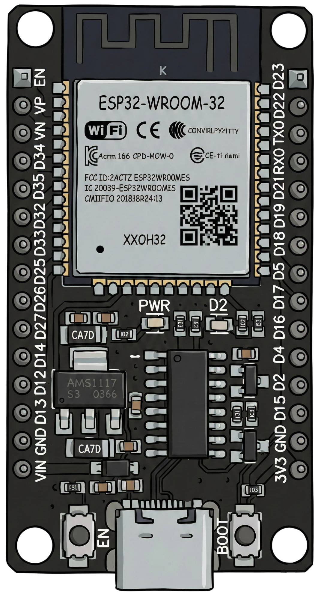
Pin Configuration and Descriptions

The ESP32-VROOM-32 module has 38 pins. Below is a table describing the key pins:

Pin Number Pin Name Description
1 EN Enable pin. Pull high to enable the module.
2 IO0 GPIO0. Used for boot mode selection during programming.
3 IO1 (TX0) GPIO1. UART0 TX pin.
4 IO3 (RX0) GPIO3. UART0 RX pin.
5 IO4 GPIO4. General-purpose I/O pin.
6 IO5 GPIO5. General-purpose I/O pin.
7 IO12 GPIO12. Can be used as an ADC or touch sensor input.
8 IO13 GPIO13. Can be used as an ADC or touch sensor input.
9 IO14 GPIO14. Supports PWM, ADC, and other functions.
10 IO15 GPIO15. Supports PWM, ADC, and other functions.
11 IO16 GPIO16. General-purpose I/O pin.
12 IO17 GPIO17. General-purpose I/O pin.
13 GND Ground pin.
14 3V3 3.3V power supply input.
15 VIN Input voltage pin (5V).

Note: For a complete pinout diagram, refer to the official datasheet provided by Diymore.

Usage Instructions

The ESP32-VROOM-32 is easy to integrate into a variety of projects. Below are the steps and best practices for using the module:

How to Use the ESP32-VROOM-32 in a Circuit

  1. Power Supply: Provide a stable 3.3V power supply to the 3V3 pin. If using the VIN pin, supply 5V.
  2. Programming: Use a USB-to-serial adapter to connect the module to your computer. Connect:
    • TX on the adapter to RX0 (IO3) on the ESP32.
    • RX on the adapter to TX0 (IO1) on the ESP32.
    • GND on the adapter to GND on the ESP32.
  3. Boot Mode: To upload code, hold the IO0 pin low (connect to GND) while resetting the module.
  4. GPIO Usage: Connect peripherals (e.g., sensors, LEDs) to the GPIO pins. Ensure the pins are not overloaded with current.

Important Considerations and Best Practices

  • Voltage Levels: The ESP32 operates at 3.3V logic levels. Avoid connecting 5V signals directly to GPIO pins.
  • Power Supply: Use a low-noise power supply to avoid interference with Wi-Fi and Bluetooth signals.
  • Heat Management: The module may heat up during operation. Ensure proper ventilation or heat dissipation.
  • Programming Environment: Use the Arduino IDE or ESP-IDF for programming. Install the necessary ESP32 board support package.

Example Code for Arduino UNO Integration

Below is an example of how to blink an LED connected to GPIO2 on the ESP32 using the Arduino IDE:

// Example: Blink an LED connected to GPIO2 on the ESP32-VROOM-32

// Define the GPIO pin for the LED
#define LED_PIN 2

void setup() {
  // Initialize the LED pin as an output
  pinMode(LED_PIN, OUTPUT);
}

void loop() {
  // Turn the LED on
  digitalWrite(LED_PIN, HIGH);
  delay(1000); // Wait for 1 second

  // Turn the LED off
  digitalWrite(LED_PIN, LOW);
  delay(1000); // Wait for 1 second
}

Tip: Ensure the ESP32 is properly connected to your computer and the correct board and port are selected in the Arduino IDE.

Troubleshooting and FAQs

Common Issues and Solutions

  1. Issue: The ESP32 is not detected by the computer.

    • Solution: Ensure the USB-to-serial adapter drivers are installed. Check the connections and ensure the module is powered.
  2. Issue: Code upload fails with a timeout error.

    • Solution: Hold the IO0 pin low (connect to GND) while resetting the module to enter boot mode.
  3. Issue: Wi-Fi connection is unstable.

    • Solution: Use a stable power supply and ensure the antenna is not obstructed.
  4. Issue: GPIO pins are not functioning as expected.

    • Solution: Verify the pin configuration in your code. Ensure the pins are not being used for other functions (e.g., boot mode).

FAQs

  • Q: Can the ESP32-VROOM-32 operate on 5V logic levels?
    A: No, the ESP32 operates at 3.3V logic levels. Use a level shifter if interfacing with 5V devices.

  • Q: What is the maximum current draw of the ESP32?
    A: The ESP32 can draw up to 500 mA during peak operation. Ensure your power supply can handle this.

  • Q: Can I use the ESP32 with a battery?
    A: Yes, you can power the ESP32 using a 3.7V LiPo battery connected to the VIN pin.

  • Q: How do I reset the ESP32?
    A: Press the EN pin or button to reset the module.

By following this documentation, you can effectively use the ESP32-VROOM-32 in your projects. For further details, refer to the official datasheet or support resources provided by Diymore.