How to Use DFRobot Stepdown : Examples, Pinouts, and Specs

Introduction
The DFRobot Stepdown (DFR1208) is a DC-DC step-down converter designed to efficiently reduce a higher input voltage to a stable, lower output voltage. This component is ideal for powering devices that require a specific voltage level, such as microcontrollers, sensors, and other electronic modules. Its compact design and high efficiency make it a versatile choice for a wide range of applications, including robotics, IoT devices, and portable electronics.
Explore Projects Built with DFRobot Stepdown
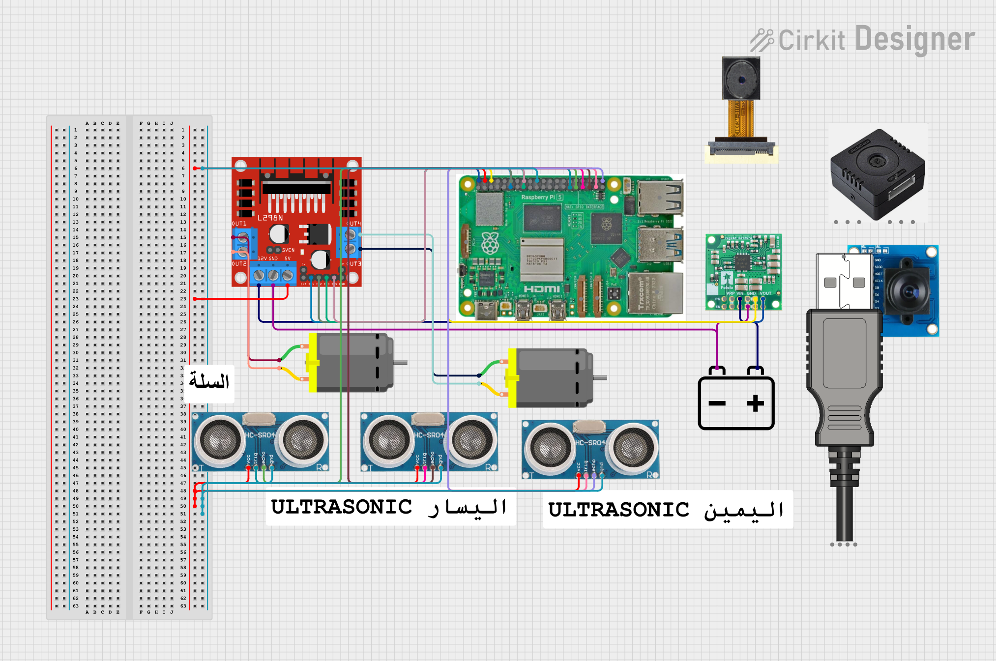

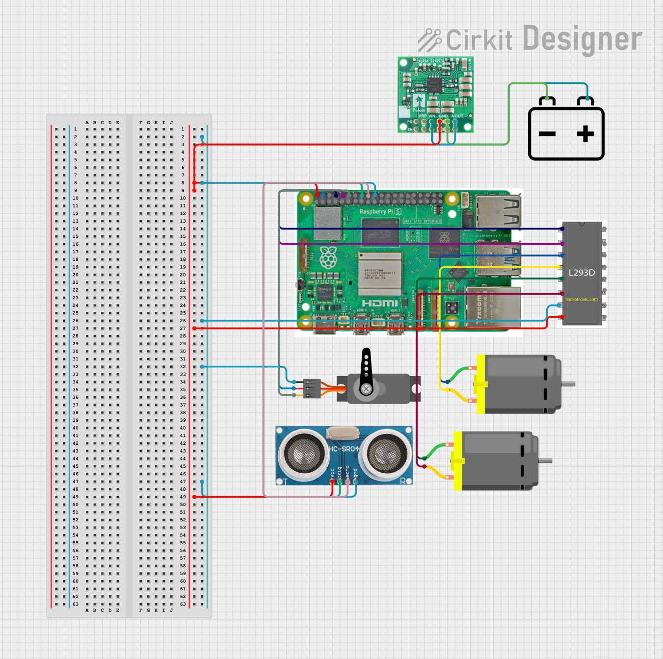

Explore Projects Built with DFRobot Stepdown
Common Applications and Use Cases
- Powering microcontrollers (e.g., Arduino, Raspberry Pi) from higher voltage sources.
- Supplying stable voltage to sensors and modules in IoT projects.
- Voltage regulation in battery-powered systems.
- Robotics and automation systems requiring multiple voltage levels.
Technical Specifications
The DFRobot Stepdown (DFR1208) offers the following key technical specifications:
| Parameter | Value |
|---|---|
| Input Voltage Range | 4.5V to 24V |
| Output Voltage Range | 0.8V to 15V (adjustable) |
| Output Current | Up to 3A |
| Efficiency | Up to 96% |
| Switching Frequency | 340 kHz |
| Operating Temperature | -40°C to +85°C |
| Dimensions | 22mm x 17mm x 4mm |
Pin Configuration and Descriptions
The DFR1208 has the following pin layout:
| Pin Name | Description |
|---|---|
| VIN | Input voltage pin. Connect to the higher voltage source (4.5V to 24V). |
| GND | Ground pin. Connect to the ground of the power source and the load circuit. |
| VOUT | Output voltage pin. Provides the regulated voltage (0.8V to 15V). |
| EN | Enable pin. Pull high to enable the module; pull low to disable it. |
| ADJ | Voltage adjustment pin. Use a potentiometer or resistor to set the output voltage. |
Usage Instructions
How to Use the Component in a Circuit
Connect the Input Voltage:
- Connect the VIN pin to the positive terminal of your power source (e.g., a 12V battery or adapter).
- Connect the GND pin to the ground of your power source.
Set the Output Voltage:
- Use the ADJ pin to adjust the output voltage. This can be done by connecting a potentiometer or a fixed resistor to set the desired voltage level.
- Measure the output voltage at the VOUT pin using a multimeter to ensure it matches your requirements.
Connect the Load:
- Connect the VOUT pin to the positive terminal of your load (e.g., a microcontroller or sensor).
- Connect the GND pin to the ground of your load.
Enable the Module:
- Ensure the EN pin is pulled high (connected to VIN or a logic high signal) to enable the module. If the EN pin is left floating or pulled low, the module will be disabled.
Important Considerations and Best Practices
- Input Voltage Range: Ensure the input voltage is within the specified range (4.5V to 24V). Exceeding this range may damage the module.
- Output Current Limit: Do not exceed the maximum output current of 3A to prevent overheating or damage.
- Heat Dissipation: For high current loads, consider adding a heatsink or ensuring proper ventilation to maintain safe operating temperatures.
- Voltage Adjustment: When adjusting the output voltage, do so gradually and monitor the voltage with a multimeter to avoid overshooting the desired value.
- Polarity Protection: Double-check the polarity of your connections to avoid damaging the module.
Example: Using the DFR1208 with an Arduino UNO
The DFR1208 can be used to power an Arduino UNO from a 12V power source. Here's how to set it up:
- Connect the VIN pin of the DFR1208 to the positive terminal of the 12V power source.
- Connect the GND pin of the DFR1208 to the ground of the power source.
- Adjust the output voltage to 5V using the ADJ pin.
- Connect the VOUT pin of the DFR1208 to the 5V pin of the Arduino UNO.
- Connect the GND pin of the DFR1208 to the GND pin of the Arduino UNO.
Here is an example Arduino code to blink an LED, powered by the DFR1208:
// This code blinks an LED connected to pin 13 of the Arduino UNO.
// Ensure the Arduino is powered by the DFR1208 with a stable 5V output.

void setup() {
  pinMode(13, OUTPUT); // Set pin 13 as an output pin
}

void loop() {
  digitalWrite(13, HIGH); // Turn the LED on
  delay(1000);            // Wait for 1 second
  digitalWrite(13, LOW);  // Turn the LED off
  delay(1000);            // Wait for 1 second
}
Troubleshooting and FAQs
Common Issues and Solutions
No Output Voltage:
- Cause: The EN pin is not pulled high.
- Solution: Ensure the EN pin is connected to VIN or a logic high signal.
Output Voltage is Incorrect:
- Cause: The ADJ pin is not properly configured.
- Solution: Recheck the resistor or potentiometer connected to the ADJ pin and adjust as needed.
Module Overheating:
- Cause: Excessive current draw or poor ventilation.
- Solution: Ensure the load does not exceed 3A and improve airflow around the module.
No Power to the Load:
- Cause: Incorrect wiring or polarity.
- Solution: Double-check all connections and ensure correct polarity.
FAQs
Q: Can the DFR1208 be used with a 24V input to power a 3.3V device?
A: Yes, the DFR1208 can step down a 24V input to 3.3V, provided the output current does not exceed 3A.
Q: Is the module protected against reverse polarity?
A: No, the DFR1208 does not have built-in reverse polarity protection. Always double-check your connections.
Q: Can I use the DFR1208 to charge a battery?
A: The DFR1208 is not specifically designed for battery charging. Use a dedicated battery charging module for this purpose.
Q: How do I know if the module is enabled?
A: Check the voltage at the VOUT pin. If the module is enabled, it will output the set voltage. If disabled, the output will be 0V.