How to Use LED 2.4W: Examples, Pinouts, and Specs

Introduction
The LED 2.4W is a Light Emitting Diode designed for efficient illumination with minimal power consumption. With a power rating of 2.4 watts, this LED offers bright and reliable lighting while maintaining a long operational lifespan and low heat generation. Its compact size and energy efficiency make it ideal for a wide range of applications.
Explore Projects Built with LED 2.4W

Explore Projects Built with LED 2.4W
Common Applications and Use Cases
- Indoor and outdoor lighting systems
- Indicator lights in electronic devices
- Automotive lighting (e.g., dashboards, tail lights)
- Decorative and architectural lighting
- DIY electronics and hobby projects
Technical Specifications
Below are the key technical details and pin configuration for the LED 2.4W:
Key Technical Details
| Parameter | Value |
|---|---|
| Power Consumption | 2.4 W |
| Forward Voltage (Vf) | 3.0 - 3.4 V |
| Forward Current (If) | 700 mA |
| Luminous Flux | 200 - 240 lumens |
| Color Temperature | 3000K (Warm White) |
| Viewing Angle | 120° |
| Lifespan | 50,000 hours (typical) |
| Operating Temperature | -20°C to +85°C |
| Package Type | SMD or through-hole |
Pin Configuration and Descriptions
| Pin Name | Description |
|---|---|
| Anode (+) | Positive terminal (connect to Vcc) |
| Cathode (-) | Negative terminal (connect to GND) |
Usage Instructions
How to Use the LED 2.4W in a Circuit
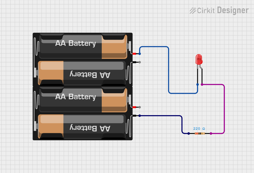
Determine the Resistor Value: To prevent damage, use a current-limiting resistor in series with the LED. Calculate the resistor value using Ohm's Law: [ R = \frac{V_{supply} - V_f}{I_f} ]
- (V_{supply}): Supply voltage
- (V_f): Forward voltage of the LED (3.0 - 3.4 V)
- (I_f): Forward current of the LED (700 mA)
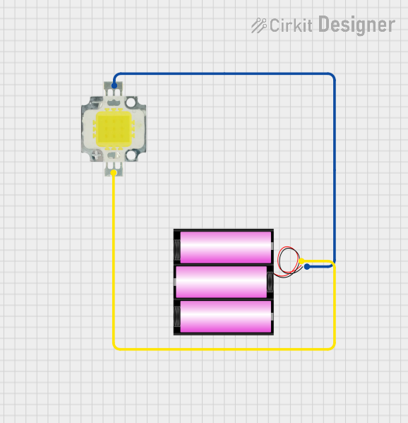
Connect the LED:
- Connect the Anode (+) to the positive terminal of the power supply through the resistor.
- Connect the Cathode (-) to the ground (GND).
Power the Circuit: Ensure the power supply matches the voltage and current requirements of the LED.
Important Considerations and Best Practices
- Heat Management: Use a heat sink or proper ventilation to dissipate heat, especially in high-power applications.
- Polarity: LEDs are polarity-sensitive. Reversing the connections can damage the component.
- Current Limiting: Always use a resistor or constant current driver to avoid overdriving the LED.
- Soldering: If using an SMD package, ensure proper soldering techniques to avoid thermal damage.
Example: Connecting LED 2.4W to an Arduino UNO
Below is an example of how to control the LED 2.4W using an Arduino UNO and a 220-ohm resistor:
// Define the pin connected to the LED
const int ledPin = 9; // PWM pin for brightness control

void setup() {
  pinMode(ledPin, OUTPUT); // Set the LED pin as an output
}

void loop() {
  analogWrite(ledPin, 128); // Set LED brightness to 50% (128 out of 255)
  delay(1000);              // Keep the LED on for 1 second
  analogWrite(ledPin, 0);   // Turn off the LED
  delay(1000);              // Keep the LED off for 1 second
}
Notes:
- Use a transistor or MOSFET if the LED requires more current than the Arduino pin can supply.
- Adjust the resistor value based on the supply voltage and LED specifications.
Troubleshooting and FAQs
Common Issues and Solutions
LED Does Not Light Up:
Cause: Incorrect polarity.
Solution: Verify that the Anode is connected to the positive terminal and the Cathode to GND.
Cause: Insufficient current or incorrect resistor value.
Solution: Recalculate the resistor value and ensure the power supply provides adequate current.
LED Flickers:
- Cause: Unstable power supply or loose connections.
- Solution: Check the power source and ensure all connections are secure.
LED Overheats:
- Cause: Excessive current or poor heat dissipation.
- Solution: Use a proper current-limiting resistor and consider adding a heat sink.
LED Burns Out Quickly:
- Cause: Overvoltage or overcurrent.
- Solution: Double-check the power supply voltage and resistor value.
FAQs
Q: Can I connect the LED 2.4W directly to a 5V power supply?
A: No, you must use a current-limiting resistor or a constant current driver to prevent overcurrent damage.
Q: How do I calculate the resistor value for a 12V power supply?
A: Use the formula (R = \frac{V_{supply} - V_f}{I_f}). For example, with (V_f = 3.2V) and (I_f = 0.7A):
[
R = \frac{12V - 3.2V}{0.7A} \approx 12.57 , \Omega
]
Choose the nearest standard resistor value (e.g., 12.5Ω or 13Ω).
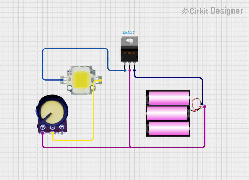
Q: Can I dim the LED 2.4W?
A: Yes, you can use a PWM signal from a microcontroller (e.g., Arduino) or a dedicated LED dimmer circuit.
Q: What happens if I reverse the polarity?
A: The LED will not light up, and prolonged reverse polarity may damage the component.
By following this documentation, you can effectively integrate the LED 2.4W into your projects and ensure optimal performance.