How to Use TIMER CY6Y-1P4: Examples, Pinouts, and Specs
Introduction
The CY6Y-1P4 is a versatile programmable timer integrated circuit (IC) designed for a wide range of timing applications in electronic circuits. It allows users to configure adjustable time intervals and supports multiple operational modes, such as delay timing, pulse generation, and oscillation. Its flexibility and ease of use make it an ideal choice for hobbyists, engineers, and designers working on projects that require precise timing control.
Explore Projects Built with TIMER CY6Y-1P4

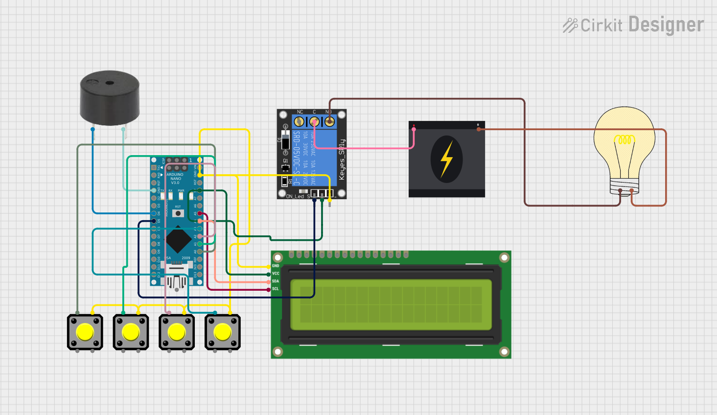
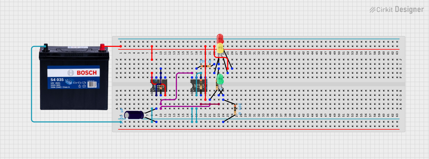
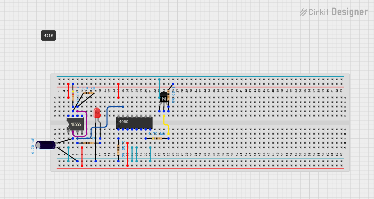
Explore Projects Built with TIMER CY6Y-1P4
Common Applications and Use Cases
- Delay timing in automation systems
- Pulse generation for triggering other components
- Oscillation for clock signal generation
- Timer-based control in embedded systems
- LED blinking circuits
- Motor control and sequencing
Technical Specifications
The CY6Y-1P4 is designed to provide reliable and accurate timing functionality. Below are its key technical details:
| Parameter | Value |
|---|---|
| Supply Voltage (Vcc) | 3.3V to 15V |
| Operating Current | 5 mA (typical) |
| Timing Range | 1 ms to 10 minutes (adjustable) |
| Output Voltage (High) | Vcc - 0.7V |
| Output Voltage (Low) | 0V |
| Output Current | 20 mA (maximum) |
| Operating Temperature | -40°C to +85°C |
| Package Type | DIP-8 or SOIC-8 |
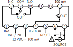
Pin Configuration and Descriptions
The CY6Y-1P4 comes in an 8-pin package. Below is the pinout and description:
| Pin Number | Pin Name | Description |
|---|---|---|
| 1 | Vcc | Positive power supply input (3.3V to 15V). |
| 2 | GND | Ground connection. |
| 3 | TRIG | Trigger input to start the timer. |
| 4 | RESET | Resets the timer when pulled low. |
| 5 | OUT | Timer output signal (high or low). |
| 6 | MODE | Selects the operating mode (delay, pulse, etc.). |
| 7 | ADJ | Connects to an external resistor/capacitor for |
| adjusting the timing interval. | ||
| 8 | NC | No connection (leave unconnected). |
Usage Instructions
The CY6Y-1P4 is straightforward to use in a variety of circuits. Below are the steps and considerations for using the component effectively:
Basic Circuit Setup
- Power Supply: Connect the Vcc pin (Pin 1) to a stable power source (3.3V to 15V) and the GND pin (Pin 2) to ground.
- Trigger Input: Apply a signal to the TRIG pin (Pin 3) to start the timer. This can be a button press or a digital signal.
- Timing Adjustment: Connect an external resistor and capacitor to the ADJ pin (Pin 7) to set the desired timing interval. The timing is determined by the RC time constant.
- Output Signal: The OUT pin (Pin 5) provides the timer's output signal, which can be used to drive LEDs, relays, or other components.
- Mode Selection: Use the MODE pin (Pin 6) to select the desired operating mode. Refer to the datasheet for specific mode configurations.
Example Circuit with Arduino UNO
The CY6Y-1P4 can be easily interfaced with an Arduino UNO for timing applications. Below is an example of a simple LED blinking circuit:
Circuit Connections
- Connect Pin 1 (Vcc) to the Arduino's 5V pin.
- Connect Pin 2 (GND) to the Arduino's GND pin.
- Connect Pin 3 (TRIG) to Arduino digital pin 2.
- Connect Pin 5 (OUT) to an LED (with a current-limiting resistor) and then to GND.
- Connect an RC network to Pin 7 (ADJ) to set the timing interval.
Arduino Code
// Example code to use CY6Y-1P4 with Arduino UNO
// This code triggers the timer and reads the output to blink an LED.

const int triggerPin = 2;  // Pin connected to TRIG (Pin 3 of CY6Y-1P4)
const int outputPin = 3;   // Pin connected to OUT (Pin 5 of CY6Y-1P4)
const int ledPin = 13;     // Built-in LED on Arduino

void setup() {
  pinMode(triggerPin, OUTPUT);  // Set trigger pin as output
  pinMode(outputPin, INPUT);    // Set output pin as input
  pinMode(ledPin, OUTPUT);      // Set LED pin as output

  digitalWrite(triggerPin, LOW);  // Ensure trigger is low initially
}

void loop() {
  // Trigger the timer
  digitalWrite(triggerPin, HIGH);  // Send a high signal to TRIG
  delay(10);                       // Short delay to ensure trigger is registered
  digitalWrite(triggerPin, LOW);   // Set trigger back to low

  // Read the timer output
  if (digitalRead(outputPin) == HIGH) {
    digitalWrite(ledPin, HIGH);  // Turn on LED if timer output is high
  } else {
    digitalWrite(ledPin, LOW);   // Turn off LED if timer output is low
  }

  delay(100);  // Small delay for stability
}
Important Considerations
- Ensure the power supply voltage is within the specified range (3.3V to 15V).
- Use appropriate resistor and capacitor values for the desired timing interval.
- Avoid leaving unused pins floating; connect them to GND or Vcc as recommended.
- For precise timing, use high-quality components with low tolerance values.
Troubleshooting and FAQs
Common Issues and Solutions
Timer Not Starting
- Ensure the TRIG pin is receiving a valid signal.
- Check the power supply connections and voltage levels.
Incorrect Timing Interval
- Verify the resistor and capacitor values connected to the ADJ pin.
- Ensure the RC network is properly connected and free of shorts.
No Output Signal
- Check the OUT pin connection and ensure the load does not exceed 20 mA.
- Verify the mode selection on the MODE pin.
Component Overheating
- Ensure the supply voltage does not exceed 15V.
- Check for short circuits or excessive current draw.
FAQs
Q: Can the CY6Y-1P4 operate at 3.3V?
A: Yes, the CY6Y-1P4 can operate at a minimum supply voltage of 3.3V.
Q: How do I calculate the timing interval?
A: The timing interval is determined by the RC time constant: T = R × C. Refer to the datasheet for detailed formulas.
Q: Can I use the CY6Y-1P4 for PWM generation?
A: While the CY6Y-1P4 is not specifically designed for PWM, it can be configured for basic pulse generation.
Q: What happens if the RESET pin is left floating?
A: The RESET pin should not be left floating. Connect it to Vcc for normal operation or pull it low to reset the timer.
By following this documentation, users can effectively integrate the CY6Y-1P4 into their projects and troubleshoot common issues with ease.