How to Use LMZ14203: Examples, Pinouts, and Specs
Introduction
The LMZ14203 is a highly efficient, easy-to-use, and reliable power module that integrates a buck converter into a compact package. This power module is designed to step down higher voltage inputs to lower voltage outputs while maintaining high efficiency, making it an ideal choice for a wide range of applications including industrial, automotive, and consumer electronics where space is at a premium and simplicity is valued.
Explore Projects Built with LMZ14203


Explore Projects Built with LMZ14203
Common Applications and Use Cases
- Point-of-load power supply for FPGAs, DSPs, and microprocessors
- Industrial control and automation systems
- Automotive power systems
- Telecommunication equipment
- Distributed power systems
Technical Specifications
Key Technical Details
- Input Voltage Range: 6V to 42V
- Output Voltage Range: 0.8V to 6V (adjustable)
- Output Current: Up to 3A
- Switching Frequency: 500 kHz (typical)
- Efficiency: Up to 95%
- Operating Temperature Range: -40°C to +125°C
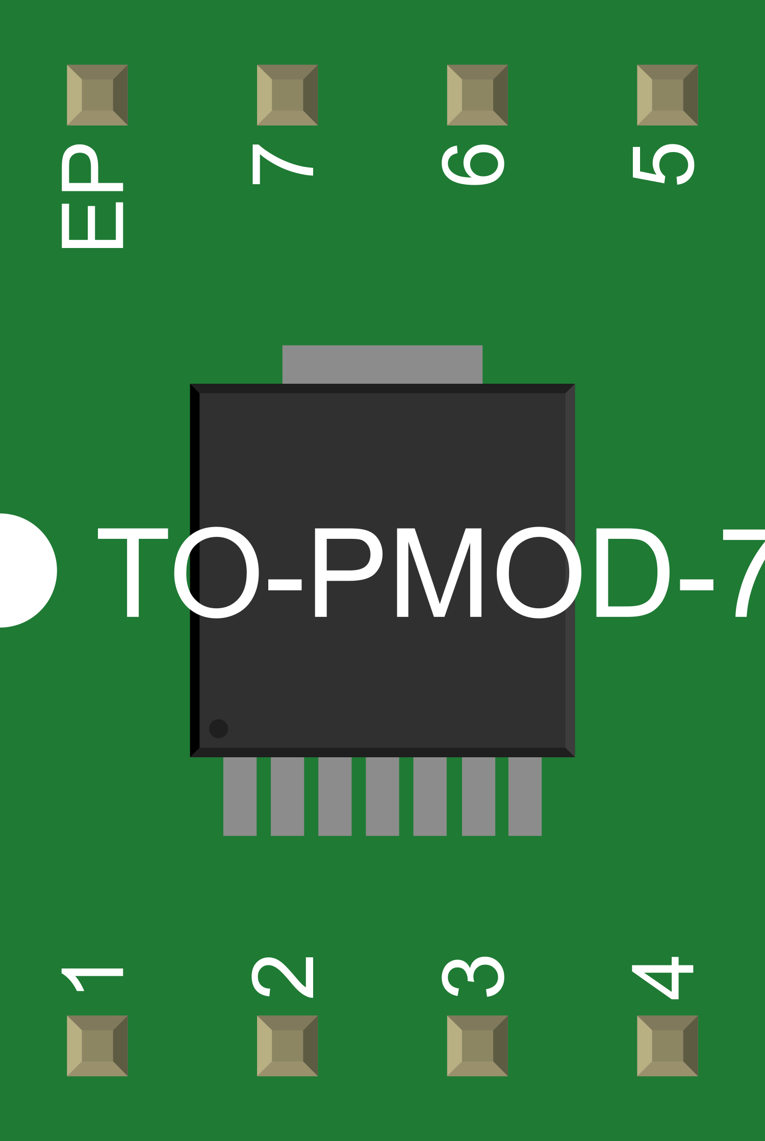
- Package: 7-pin TO-PMOD-7
Pin Configuration and Descriptions
| Pin Number | Name | Description |
|---|---|---|
| 1 | VIN | Input voltage to the module. Connect to the source voltage. |
| 2 | GND | Ground reference for the module. |
| 3 | VOUT | Regulated output voltage. Connect to the load. |
| 4 | FB | Feedback pin for output voltage regulation. |
| 5 | ON/OFF | Enables or disables the module when driven high/low. |
| 6 | SS/TR | Soft-start and tracking pin. Controls the start-up time. |
| 7 | PG | Power good. Open-drain output that indicates when VOUT is within regulation. |
Usage Instructions
How to Use the Component in a Circuit
- Input Supply: Connect a voltage source within the specified input voltage range to the VIN pin (Pin 1) and connect the ground to the GND pin (Pin 2).
- Output Load: Connect your load to the VOUT pin (Pin 3) and to the ground.
- Feedback Network: Connect a resistor divider from VOUT to FB (Pin 4) and to ground to set the output voltage.
- Enable/Disable: To enable the module, apply a high logic level to the ON/OFF pin (Pin 5). To disable, connect it to ground.
- Soft-Start: Connect a capacitor to the SS/TR pin (Pin 6) to set the soft-start time.
- Power Good Indicator: Connect a pull-up resistor to the PG pin (Pin 7) to indicate when the output is within regulation.
Important Considerations and Best Practices
- Ensure that the input voltage does not exceed the maximum rating to prevent damage.
- Use appropriate heat sinking or airflow if operating at high output currents or in high ambient temperatures.
- Place input and output capacitors close to the module to minimize noise and ensure stability.
- Use a pull-up resistor of 10kΩ for the PG pin to ensure proper logic level reading.
- Follow the recommended PCB layout guidelines provided in the datasheet for optimal performance.
Troubleshooting and FAQs
Common Issues Users Might Face
- Output Voltage Not Regulated: Check the feedback network for proper resistor values and connections.
- Module Does Not Start: Ensure that the ON/OFF pin is driven high and that the input voltage is within the specified range.
- Overheating: Verify that the load current does not exceed the maximum rating and that adequate cooling is provided.
Solutions and Tips for Troubleshooting
- If the output voltage is incorrect, recheck the feedback resistor divider and adjust the values accordingly.
- For start-up issues, ensure that the soft-start capacitor value is correct and that there are no shorts on the ON/OFF pin.
- In case of overheating, improve heat dissipation by adding a heatsink or improving airflow around the module.
FAQs
Q: Can I adjust the switching frequency of the LMZ14203? A: No, the switching frequency is internally set and cannot be adjusted.
Q: What is the maximum output current the LMZ14203 can provide? A: The module can provide up to 3A of continuous output current.
Q: How do I set the output voltage? A: The output voltage is set by a resistor divider connected from the VOUT to the FB pin and to ground. The datasheet provides a formula to calculate the resistor values for the desired output voltage.
Q: Is it necessary to use a soft-start capacitor? A: While not strictly necessary, using a soft-start capacitor can prevent inrush current at startup and provide a smoother ramp-up of the output voltage.
Q: What should I do if the PG pin does not indicate that the power is good? A: Check the pull-up resistor on the PG pin and ensure that the output voltage is within the regulation range. If the issue persists, verify the integrity of the feedback network and the load conditions.
Example Code for Arduino UNO
// Example code to monitor the Power Good status of the LMZ14203 using an Arduino UNO

const int pgPin = 2; // Connect the PG pin of LMZ14203 to digital pin 2 on Arduino

void setup() {
  pinMode(pgPin, INPUT); // Set the PG pin as an input
  Serial.begin(9600);   // Start serial communication at 9600 baud
}

void loop() {
  int powerGood = digitalRead(pgPin); // Read the status of the PG pin

  if (powerGood == HIGH) {
    Serial.println("Power is good."); // Output voltage is within regulation
  } else {
    Serial.println("Power is not good."); // Output voltage is out of regulation
  }

  delay(1000); // Wait for 1 second before reading the status again
}
This example code sets up an Arduino UNO to read the status of the Power Good (PG) pin from the LMZ14203 module. It prints a message to the serial monitor indicating whether the power is good or not. Make sure to connect a pull-up resistor to the PG pin as per the module's requirements.