How to Use DPDT Relay Base Layout: Examples, Pinouts, and Specs
Introduction
A Double Pole Double Throw (DPDT) relay base layout is a configuration used to connect a DPDT relay to a circuit. This layout facilitates the control of two independent circuits using a single relay, making it highly versatile for switching applications. DPDT relays are commonly used in automation, motor control, and signal routing, where precise control of multiple circuits is required.
Explore Projects Built with DPDT Relay Base Layout


Explore Projects Built with DPDT Relay Base Layout
Common Applications and Use Cases
- Motor Direction Control: Reversing the polarity of DC motors.
- Signal Switching: Routing signals between different devices or circuits.
- Power Switching: Controlling two separate power circuits simultaneously.
- Automation Systems: Used in industrial and home automation for controlling multiple devices.
Technical Specifications
Below are the key technical details for a typical DPDT relay base layout:
General Specifications
- Relay Type: Double Pole Double Throw (DPDT)
- Operating Voltage: 5V, 12V, or 24V (depending on the relay used)
- Contact Rating: Typically 10A at 250VAC or 30VDC
- Coil Resistance: Varies based on operating voltage (e.g., ~70Ω for 5V relays)
- Switching Mechanism: Electromagnetic
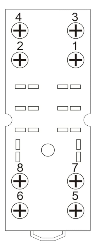
- Number of Pins: 8 pins (2 for the coil, 6 for the contacts)
Pin Configuration and Descriptions
The DPDT relay base layout typically consists of 8 pins. The table below describes each pin:
| Pin Number | Name | Description |
|---|---|---|
| 1 | Coil (+) | Positive terminal of the relay coil. |
| 2 | Coil (-) | Negative terminal of the relay coil. |
| 3 | Common 1 (COM1) | Common terminal for the first pole of the relay. |
| 4 | Normally Open 1 (NO1) | Normally open contact for the first pole. Connects to COM1 when the relay is activated. |
| 5 | Normally Closed 1 (NC1) | Normally closed contact for the first pole. Connects to COM1 when the relay is inactive. |
| 6 | Common 2 (COM2) | Common terminal for the second pole of the relay. |
| 7 | Normally Open 2 (NO2) | Normally open contact for the second pole. Connects to COM2 when the relay is activated. |
| 8 | Normally Closed 2 (NC2) | Normally closed contact for the second pole. Connects to COM2 when the relay is inactive. |
Usage Instructions
How to Use the DPDT Relay Base Layout in a Circuit
Connect the Coil:
- Attach the positive terminal of the power supply to the Coil (+) pin.
- Connect the negative terminal of the power supply to the Coil (-) pin.
- Ensure the voltage matches the relay's operating voltage (e.g., 5V, 12V, or 24V).
Connect the Load:
- For the first circuit, connect the load between COM1 and either NO1 or NC1, depending on the desired behavior.
- For the second circuit, connect the load between COM2 and either NO2 or NC2.
Control the Relay:
- Apply the appropriate voltage to the coil to activate the relay. When activated, the NO contacts will close, and the NC contacts will open.
Test the Circuit:
- Verify that the relay switches correctly by toggling the control voltage and observing the behavior of the connected loads.
Important Considerations and Best Practices
- Diode Protection: Always place a flyback diode across the relay coil to protect the circuit from voltage spikes when the relay is deactivated.
- Power Ratings: Ensure the relay's contact ratings are not exceeded to avoid damage.
- Isolation: Use optocouplers or transistors to isolate the control circuit from the relay if necessary.
- Secure Connections: Ensure all connections are tight and secure to prevent loose contacts.
Example: Connecting a DPDT Relay to an Arduino UNO
Below is an example of how to control a DPDT relay using an Arduino UNO:
// Define the pin connected to the relay module
const int relayPin = 7;

void setup() {
  pinMode(relayPin, OUTPUT); // Set the relay pin as an output
  digitalWrite(relayPin, LOW); // Ensure the relay is off initially
}

void loop() {
  digitalWrite(relayPin, HIGH); // Activate the relay
  delay(2000); // Keep the relay on for 2 seconds
  digitalWrite(relayPin, LOW); // Deactivate the relay
  delay(2000); // Keep the relay off for 2 seconds
}
Note: Ensure the relay module is compatible with the Arduino's output voltage (typically 5V). Use an external power supply if the relay requires higher voltage.
Troubleshooting and FAQs
Common Issues and Solutions
Relay Not Activating:
- Cause: Insufficient voltage or current to the coil.
- Solution: Verify the power supply voltage and current match the relay's specifications.
Contacts Not Switching:
- Cause: Faulty relay or incorrect wiring.
- Solution: Check the wiring and test the relay with a multimeter.
Voltage Spikes Damaging Components:
- Cause: Lack of a flyback diode across the coil.
- Solution: Install a diode (e.g., 1N4007) across the coil terminals, with the cathode connected to Coil (+).
Relay Buzzing Noise:
- Cause: Insufficient or unstable power supply.
- Solution: Use a stable power source and ensure proper connections.
FAQs
Q: Can I use a DPDT relay for AC and DC loads simultaneously?
A: Yes, but ensure the relay's contact ratings are suitable for both AC and DC loads.Q: How do I reverse a motor's direction using a DPDT relay?
A: Connect the motor to the NO and NC contacts of one pole, and use the COM terminal to switch the polarity.Q: Can I control a DPDT relay directly from a microcontroller?
A: Yes, but use a transistor or relay driver circuit if the relay requires more current than the microcontroller can provide.
By following this documentation, you can effectively integrate a DPDT relay base layout into your projects for reliable and versatile circuit control.