How to Use Myoware 2.0 Muscle Sensor: Examples, Pinouts, and Specs
Introduction
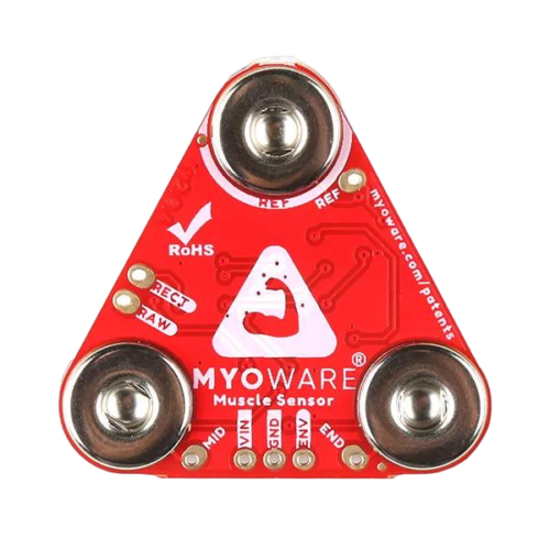
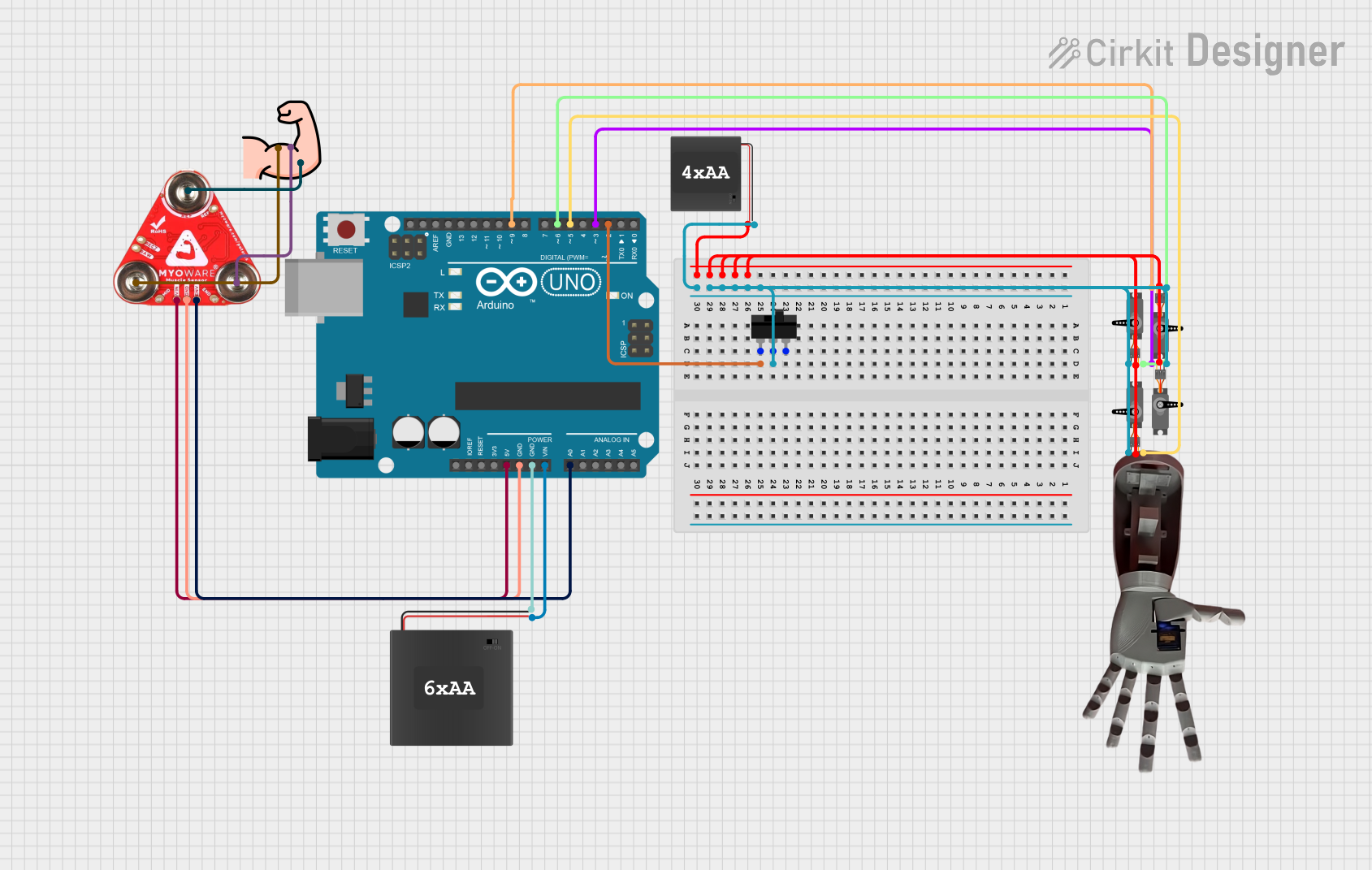
The Myoware 2.0 Muscle Sensor (part ID: DEV-21265) is an advanced device designed to measure the electrical activity of muscles, known as electromyography (EMG). This sensor is capable of detecting the electrical potential generated by muscle cells when these cells are electrically or neurologically activated. It is commonly used in biofeedback, physical therapy, prosthetics, and gesture-controlled systems. The sensor's non-invasive design makes it suitable for hobbyist projects and research applications alike.
Explore Projects Built with Myoware 2.0 Muscle Sensor
Explore Projects Built with Myoware 2.0 Muscle Sensor
Technical Specifications
Key Technical Details
- Supply Voltage: 3.3V to 5V
- Output Voltage: 0V - Vcc
- Current Consumption: Typically <10mA
- Analog Output: Proportional to the amount of muscle activity
- Connector: Standard 3-pin 0.1" pitch header
Pin Configuration and Descriptions
| Pin Number | Name | Description |
|---|---|---|
| 1 | SIG | Analog signal output proportional to muscle activity |
| 2 | +V | Power supply input (3.3V to 5V) |
| 3 | GND | Ground connection |
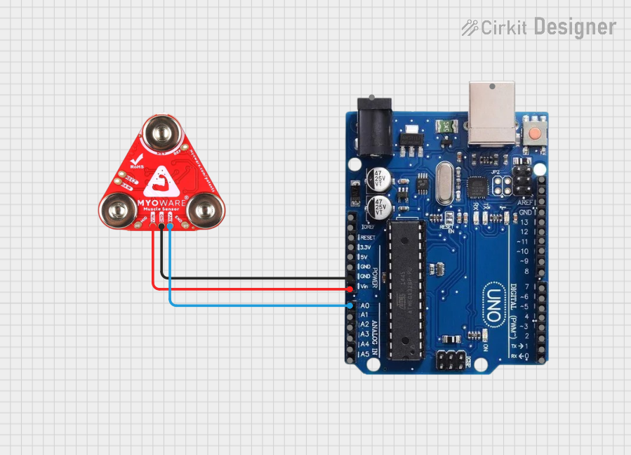
Usage Instructions
Integration with a Circuit
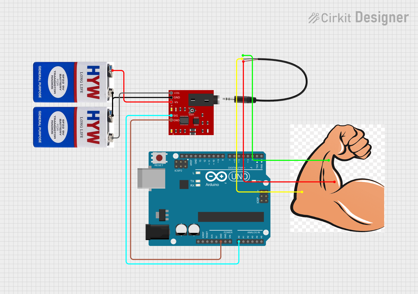
To use the Myoware 2.0 Muscle Sensor in a circuit, follow these steps:
- Connect the
+Vpin to a 3.3V or 5V power supply. - Connect the
GNDpin to the ground of the power supply. - Connect the
SIGpin to an analog input on your microcontroller (e.g., Arduino UNO).
Important Considerations and Best Practices
- Ensure that the power supply voltage does not exceed the recommended range.
- Place the sensor firmly against the skin over the muscle you wish to measure.
- Use a high-quality, low-noise power supply to minimize signal interference.
- Keep the sensor away from electrical noise sources such as motors and high-current traces.
Example Code for Arduino UNO
// Myoware 2.0 Muscle Sensor Example Code for Arduino UNO
int muscleSensorPin = A0; // Connect the sensor's SIG pin to A0
int muscleSensorValue = 0; // Variable to store the sensor value

void setup() {
  Serial.begin(9600); // Start serial communication at 9600 baud
}

void loop() {
  muscleSensorValue = analogRead(muscleSensorPin); // Read the sensor value
  Serial.println(muscleSensorValue); // Print the sensor value to the serial monitor
  delay(10); // Short delay for stability
}
Troubleshooting and FAQs
Common Issues
- Inconsistent Readings: Ensure that the sensor is properly placed on the skin and that the skin is clean.
- No Signal: Check all connections, especially the power supply and ground connections.
- Noise in Signal: Use a low-noise power supply and keep the sensor away from noise sources.
Solutions and Tips
- Improving Signal Quality: Use conductive gel or pads to improve the contact between the sensor and the skin.
- Calibration: You may need to calibrate the sensor for different muscle groups or individuals.
- Filtering: Implement software filtering techniques to smooth out the signal if necessary.
FAQs
Q: Can I use the Myoware 2.0 Muscle Sensor with a 3.3V system? A: Yes, the sensor can operate at 3.3V to 5V.
Q: How do I know if the sensor is working correctly? A: When connected to a microcontroller and the provided code is running, you should see varying analog values in the serial monitor as the muscle contracts and relaxes.
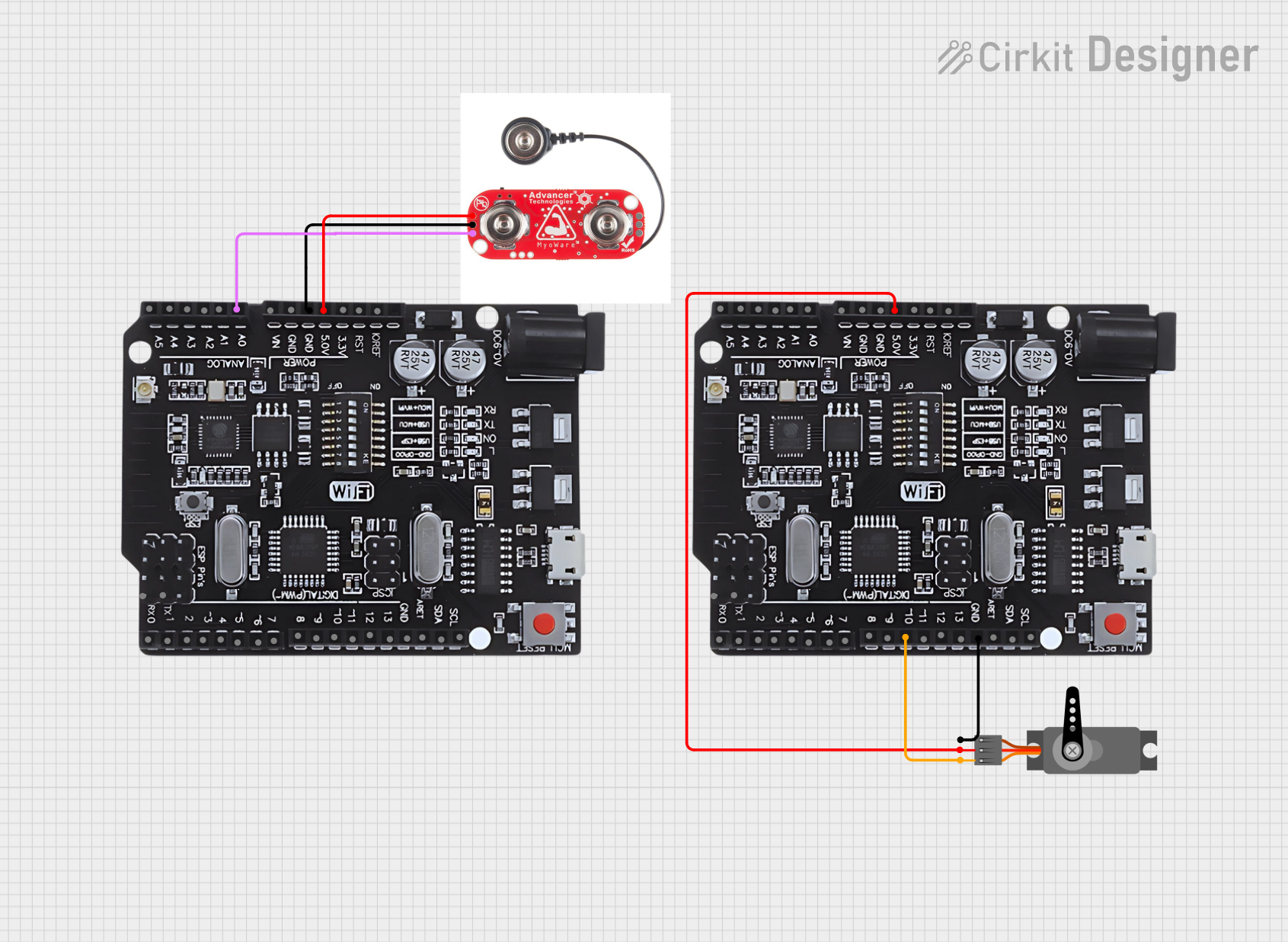
Q: Is it possible to connect multiple Myoware sensors to a single microcontroller? A: Yes, you can connect multiple sensors to different analog pins on the microcontroller.
Remember to consult the manufacturer's datasheet for more detailed information and contact technical support if you encounter issues beyond the scope of this documentation.