Cirkit Designer
Your all-in-one circuit design IDE
Home /
Component Documentation
How to Use Sonda Sensor TDS: Examples, Pinouts, and Specs
Introduction
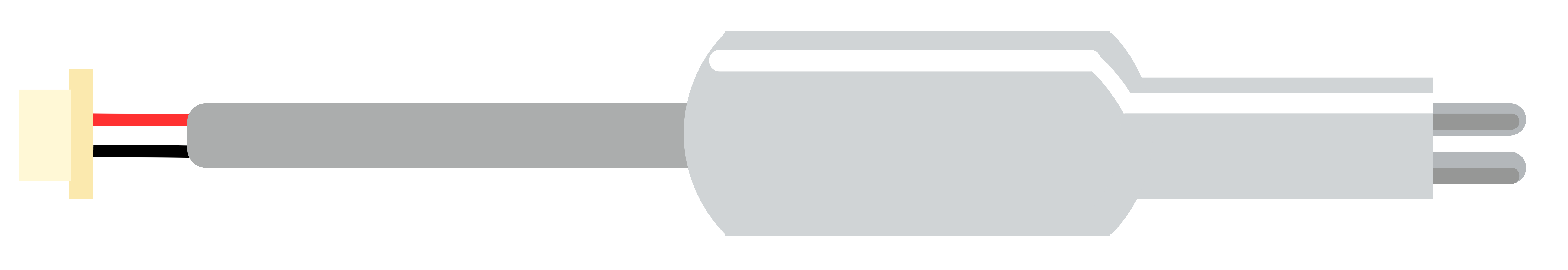
The Sonda Sensor TDS (Total Dissolved Solids) is an electronic device designed to measure the concentration of dissolved solids in a liquid. TDS is typically expressed in parts per million (ppm) and is indicative of water quality. This sensor is widely used in applications such as water purification systems, environmental monitoring, aquariums, and hydroponics to ensure the water is suitable for its intended use.
Explore Projects Built with Sonda Sensor TDS
ESP32-Based TDS Meter for Water Quality Monitoring
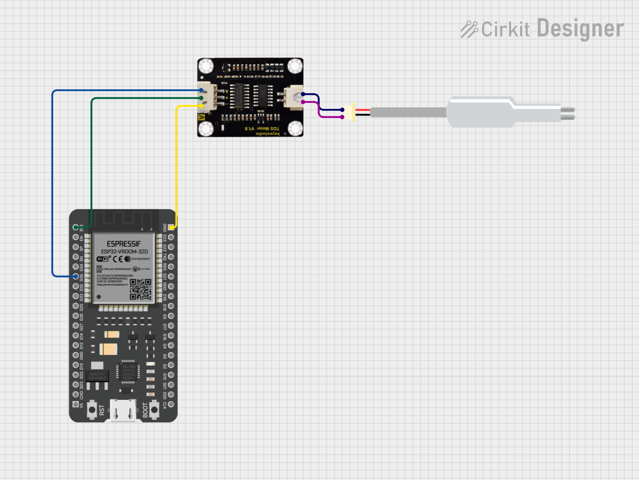
This circuit connects a TDS (Total Dissolved Solids) sensor to an ESP32 microcontroller. The TDS sensor's power is supplied by the ESP32's 3.3V and ground pins, and its analog output is connected to GPIO 35 of the ESP32 for measurement. The purpose of this circuit is to enable the ESP32 to read the TDS level of a solution, which is commonly used in water quality testing.
Arduino UNO R4 WiFi-Based Water Quality Monitoring System
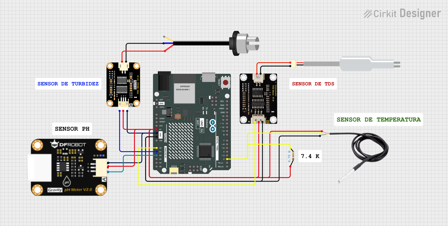
This circuit is designed for water quality monitoring, featuring an Arduino UNO R4 WiFi microcontroller connected to a TDS sensor, a DS18B20 temperature sensor, a pH sensor, and a turbidity sensor. The Arduino collects data from these sensors to assess water characteristics, with a resistor used for signal conditioning on the temperature sensor.
Arduino UNO R4 WiFi-Based Water Quality Monitoring System with TDS, pH, and Turbidity Sensors
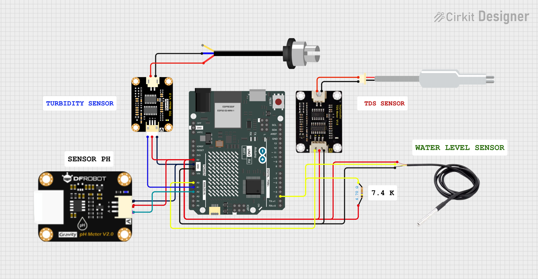
This circuit is designed for water quality monitoring, utilizing an Arduino UNO R4 WiFi to interface with various sensors including a TDS sensor, a DS18B20 temperature sensor, a pH sensor, and a turbidity sensor. The Arduino collects data from these sensors and can potentially transmit the information wirelessly for further analysis.
Arduino UNO-Based Water Quality Monitoring System with TDS Sensor and SMS Alerts
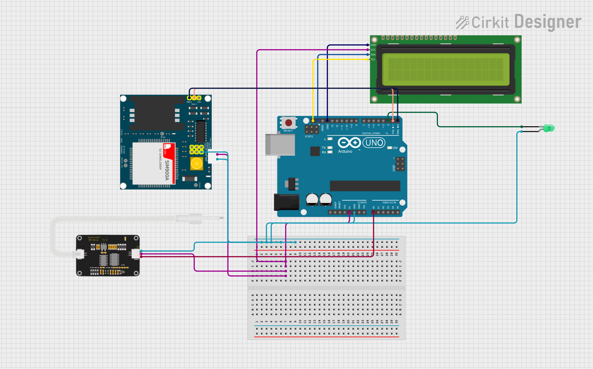
This circuit is a water quality monitoring system that uses an Arduino Uno to read TDS (Total Dissolved Solids) values from a TDS sensor and display the results on a 16x2 I2C LCD. A green LED indicates good water quality, while a SIM900A module sends an SMS alert if the water quality is poor.
Explore Projects Built with Sonda Sensor TDS
ESP32-Based TDS Meter for Water Quality Monitoring
This circuit connects a TDS (Total Dissolved Solids) sensor to an ESP32 microcontroller. The TDS sensor's power is supplied by the ESP32's 3.3V and ground pins, and its analog output is connected to GPIO 35 of the ESP32 for measurement. The purpose of this circuit is to enable the ESP32 to read the TDS level of a solution, which is commonly used in water quality testing.
Arduino UNO R4 WiFi-Based Water Quality Monitoring System
This circuit is designed for water quality monitoring, featuring an Arduino UNO R4 WiFi microcontroller connected to a TDS sensor, a DS18B20 temperature sensor, a pH sensor, and a turbidity sensor. The Arduino collects data from these sensors to assess water characteristics, with a resistor used for signal conditioning on the temperature sensor.
Arduino UNO R4 WiFi-Based Water Quality Monitoring System with TDS, pH, and Turbidity Sensors
This circuit is designed for water quality monitoring, utilizing an Arduino UNO R4 WiFi to interface with various sensors including a TDS sensor, a DS18B20 temperature sensor, a pH sensor, and a turbidity sensor. The Arduino collects data from these sensors and can potentially transmit the information wirelessly for further analysis.
Arduino UNO-Based Water Quality Monitoring System with TDS Sensor and SMS Alerts
This circuit is a water quality monitoring system that uses an Arduino Uno to read TDS (Total Dissolved Solids) values from a TDS sensor and display the results on a 16x2 I2C LCD. A green LED indicates good water quality, while a SIM900A module sends an SMS alert if the water quality is poor.
Common Applications and Use Cases
- Water quality testing for drinking water
- Monitoring and controlling TDS levels in aquariums
- Hydroponic nutrient level measurement
- Industrial water processing
- Environmental water analysis
Technical Specifications
Key Technical Details
- Measurement Range: 0-9990 ppm
- Accuracy: ±2% F.S.
- Operating Voltage: 3.3V to 5.5V
- Output Voltage: 0-2.3V (corresponding to 0-4.7V input)
- Response Time: <1s
- Operating Temperature: 0-50°C
Pin Configuration and Descriptions
| Pin Number | Name | Description |
|---|---|---|
| 1 | VCC | Power supply (3.3V to 5.5V) |
| 2 | GND | Ground connection |
| 3 | AOUT | Analog output voltage |
| 4 | NC | Not connected |
Usage Instructions
How to Use the Component in a Circuit
- Connect the VCC pin to a 3.3V or 5V power supply.
- Connect the GND pin to the ground of the power supply.
- Connect the AOUT pin to an analog input on your microcontroller (e.g., Arduino UNO).
Important Considerations and Best Practices
- Ensure the sensor is properly calibrated before use.
- Avoid touching the sensor electrodes to prevent contamination and inaccurate readings.
- The sensor should be submerged in the liquid with the electrodes fully immersed.
- Regularly clean the sensor to maintain accuracy.
- Use a pull-down resistor if necessary to stabilize the output signal.
Example Code for Arduino UNO
// Define the TDS sensor's output pin
const int TdsSensorPin = A0;

void setup() {
  // Initialize serial communication at 9600 baud rate
  Serial.begin(9600);
}

void loop() {
  // Read the analog value from sensor
  int analogValue = analogRead(TdsSensorPin);

  // Convert the analog value to TDS value
  float voltage = analogValue * 5.0 / 1024.0;
  float tdsValue = (133.42 * voltage * voltage * voltage - 255.86 * voltage * voltage + 857.39 * voltage) * 0.5;

  // Print the TDS value to the serial monitor
  Serial.print("TDS Value: ");
  Serial.print(tdsValue);
  Serial.println(" ppm");

  // Wait for a second before taking the next reading
  delay(1000);
}
Code Comments
TdsSensorPin: Analog pin to which the sensor is connected.analogRead(TdsSensorPin): Reads the analog value from the sensor.voltage: Converts the analog value to voltage.tdsValue: Calculates the TDS value based on the voltage.Serial.print: Outputs the TDS value to the serial monitor.delay(1000): Pauses the loop for one second between readings.
Troubleshooting and FAQs
Common Issues Users Might Face
- Inaccurate Readings: Ensure the sensor is calibrated correctly and that the electrodes are clean.
- No Readings: Check the connections to the Arduino and ensure the sensor is powered.
- Fluctuating Readings: Stabilize the sensor in the liquid and use a pull-down resistor if necessary.
Solutions and Tips for Troubleshooting
- Calibration: Follow the manufacturer's instructions to calibrate the sensor using a standard solution.
- Cleaning: Gently clean the sensor electrodes with distilled water and a soft brush.
- Stabilization: Secure the sensor in the liquid to prevent movement that could affect readings.
FAQs
Q: Can the sensor be used in saltwater?
- A: Yes, but ensure it is within the sensor's measurement range and is calibrated for saltwater.
Q: How often should the sensor be calibrated?
- A: Calibration frequency depends on usage, but typically once every month or after any maintenance.
Q: Is it necessary to use a pull-down resistor?
- A: It may be necessary if you observe fluctuating readings due to a floating analog input. A 10kΩ resistor from AOUT to GND can help stabilize the readings.