
How to Use Header 2: Examples, Pinouts, and Specs
 Design with Header 2 in Cirkit Designer
Introduction
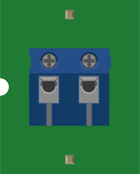
A Header 2 is a type of connector used to interface with printed circuit boards (PCBs). It typically features two rows of pins, making it ideal for secure and reliable connections in electronic circuits. These connectors are widely used in applications requiring modularity, such as prototyping, development boards, and embedded systems. Header 2 connectors are available in various pin counts and configurations, making them versatile for a wide range of projects.
Explore Projects Built with Header 2
 Open Project in Cirkit Designer
 Open Project in Cirkit Designer
 Open Project in Cirkit Designer
 Open Project in Cirkit Designer
Explore Projects Built with Header 2
Open Project in Cirkit DesignerOpen Project in Cirkit DesignerOpen Project in Cirkit DesignerOpen Project in Cirkit DesignerCommon Applications and Use Cases
- Connecting peripherals to microcontroller boards (e.g., Arduino, Raspberry Pi)
- Modular PCB designs for easy assembly and disassembly
- Prototyping and breadboarding
- Interfacing sensors, displays, and other components
- Power and signal transmission in embedded systems
Technical Specifications
Key Technical Details
- Pin Configuration: Dual-row (2xN pins, where N is the number of pins per row)
- Pitch: Typically 2.54 mm (0.1 inch) between pins
- Current Rating: Up to 3A per pin (varies by manufacturer)
- Voltage Rating: Up to 250V (varies by manufacturer)
- Material: Gold-plated or tin-plated brass pins, plastic housing
- Operating Temperature: -40°C to +105°C (typical)
Pin Configuration and Descriptions
The pin configuration of a Header 2 connector depends on the number of pins per row. Below is an example for a 2x4 (8-pin) Header 2 connector:
| Pin Number | Description | Notes |
|---|---|---|
| 1 | Signal/Power Line 1 | Can be used for data or power |
| 2 | Signal/Power Line 2 | Can be used for data or power |
| 3 | Signal/Power Line 3 | Can be used for data or power |
| 4 | Signal/Power Line 4 | Can be used for data or power |
| 5 | Signal/Power Line 5 | Can be used for data or power |
| 6 | Signal/Power Line 6 | Can be used for data or power |
| 7 | Signal/Power Line 7 | Can be used for data or power |
| 8 | Signal/Power Line 8 | Can be used for data or power |
Note: The actual pin usage depends on the circuit design and application.
Usage Instructions
How to Use the Component in a Circuit
- Soldering:
- Align the Header 2 connector with the PCB holes.
- Solder each pin securely to the PCB pads, ensuring no solder bridges between adjacent pins.
- Mating:
- Connect a compatible female header or ribbon cable to the Header 2 connector.
- Ensure proper alignment to avoid misconnection or damage.
- Wiring:
- Use the pins for signal, power, or ground connections as per your circuit design.
- Verify the pinout to avoid incorrect wiring.
Important Considerations and Best Practices
- Pin Alignment: Ensure the connector is properly aligned with the PCB to avoid mechanical stress.
- Current and Voltage Ratings: Do not exceed the specified ratings to prevent overheating or damage.
- Plating Material: For high-reliability applications, use gold-plated connectors to reduce oxidation and improve conductivity.
- Mechanical Stability: Use standoffs or mounting hardware if necessary to secure the connector in place.
Example: Connecting Header 2 to an Arduino UNO
Below is an example of using a Header 2 connector to interface with an Arduino UNO:
// Example: Reading a digital signal from a Header 2 pin connected to Arduino

const int headerPin = 2; // Pin 2 on Arduino connected to Header 2 signal pin

void setup() {
  pinMode(headerPin, INPUT); // Set the pin as input
  Serial.begin(9600);       // Initialize serial communication
}

void loop() {
  int signal = digitalRead(headerPin); // Read the signal from Header 2
  Serial.println(signal);             // Print the signal value to the Serial Monitor
  delay(500);                         // Wait for 500ms before reading again
}
Note: Ensure the Header 2 pin connected to the Arduino is properly configured in your circuit.
Troubleshooting and FAQs
Common Issues Users Might Face
Loose Connections:
- Problem: The connector feels loose or unstable.
- Solution: Ensure the pins are properly soldered and the mating connector is securely attached.
Signal Interference:
- Problem: Noise or interference in the signal lines.
- Solution: Use shorter wires and proper grounding to minimize interference.
Overheating:
- Problem: The connector gets hot during operation.
- Solution: Check the current and voltage ratings. Reduce the load if necessary.
Misaligned Connections:
- Problem: The connector is not properly aligned with the mating part.
- Solution: Double-check the alignment before connecting.
Solutions and Tips for Troubleshooting
- Use a multimeter to verify continuity and check for short circuits.
- Inspect solder joints for cold soldering or bridges.
- Refer to the datasheet of the specific Header 2 connector for detailed specifications and guidelines.
By following these instructions and best practices, you can effectively use a Header 2 connector in your electronic projects.