Cirkit Designer Logo
Cirkit Designer
Your all-in-one circuit design IDE
Home / 
Component Documentation

How to Use Adafruit PCA9685 PWM Servo Breakout: Examples, Pinouts, and Specs

Image of Adafruit PCA9685 PWM Servo Breakout
Cirkit Designer LogoDesign with Adafruit PCA9685 PWM Servo Breakout in Cirkit Designer

Introduction

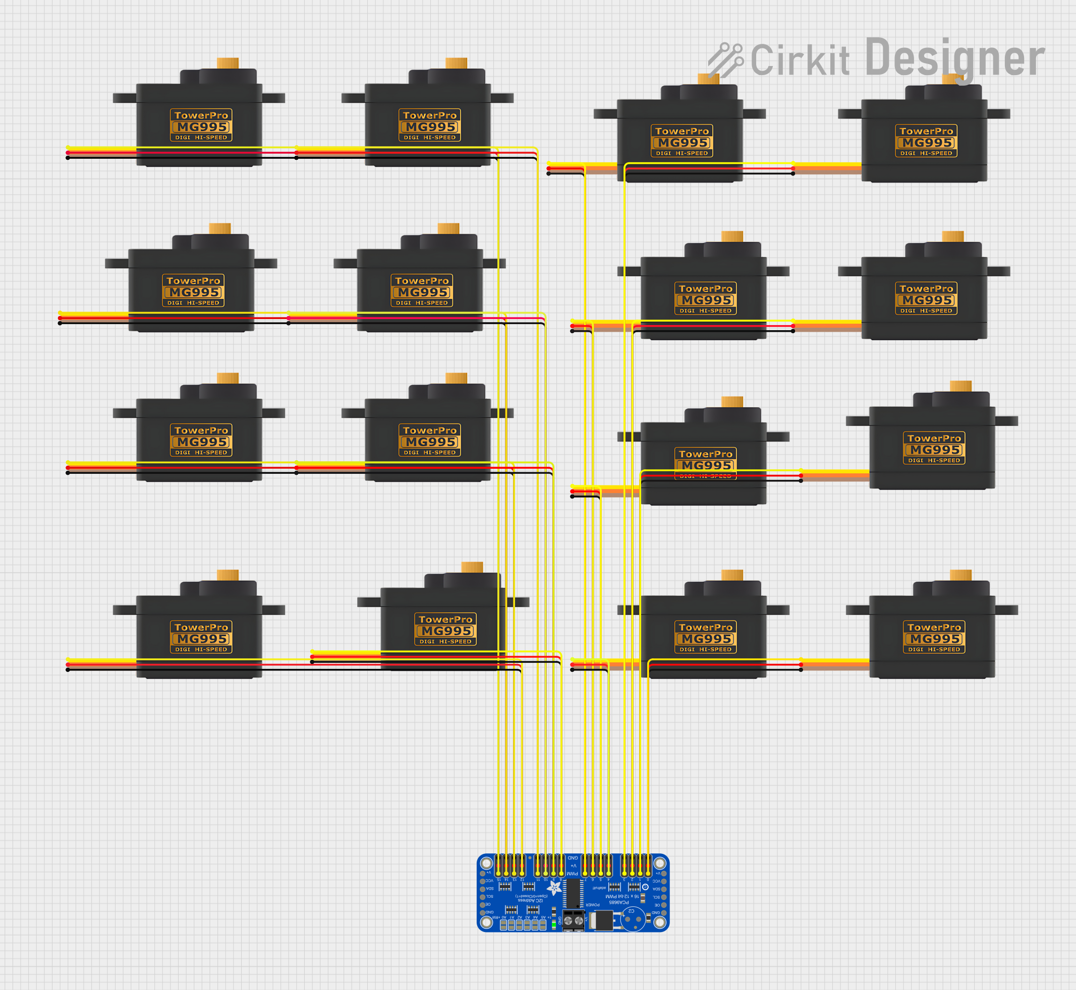
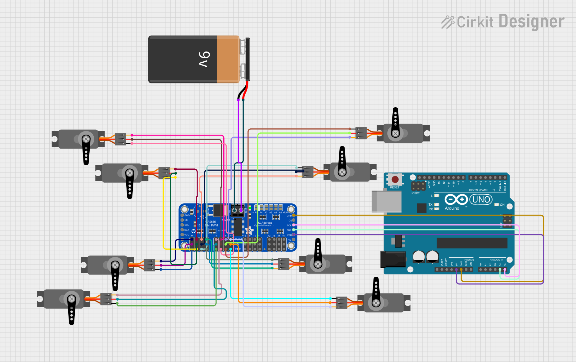
The Adafruit PCA9685 PWM Servo Breakout is a versatile and user-friendly breakout board based on the PCA9685 PWM driver IC. It enables the control of up to 16 servos or PWM outputs through just two pins (SDA and SCL) from a microcontroller, such as an Arduino UNO. This component is ideal for robotics, animatronics, lighting control, and any application requiring multiple PWM outputs. It supports both 3.3V and 5V logic levels, making it compatible with a wide range of microcontrollers.

Explore Projects Built with Adafruit PCA9685 PWM Servo Breakout

Use Cirkit Designer to design, explore, and prototype these projects online. Some projects support real-time simulation. Click "Open Project" to start designing instantly!
16-Channel Servo Controller with Adafruit PCA9685
Image of my first project: A project utilizing Adafruit PCA9685 PWM Servo Breakout in a practical application
This circuit consists of an Adafruit PCA9685 PWM Servo Breakout board connected to multiple MG995 servomotors. The PCA9685 board is used to provide PWM (Pulse Width Modulation) signals to control the position of each servomotor. Power (5V and GND) is distributed from the PCA9685 to all servomotors, and individual PWM outputs from the PCA9685 are connected to the signal inputs of the servomotors, allowing for independent control of each servomotor's angle or speed.
Cirkit Designer LogoOpen Project in Cirkit Designer
Arduino Nano and PCA9685 PWM Servo Controller for Multi-Servo Robotic Arm
Image of BRAZOS_CABEZA: A project utilizing Adafruit PCA9685 PWM Servo Breakout in a practical application
This circuit uses an Arduino Nano to control multiple servos via an Adafruit PCA9685 PWM Servo Breakout. The servos are powered by a 5V power supply, and the Arduino communicates with the PWM breakout over I2C to send control signals to the servos.
Cirkit Designer LogoOpen Project in Cirkit Designer
Arduino Mega 2560 Controlled Servo Motor with IR Remote and PWM Control
Image of project: A project utilizing Adafruit PCA9685 PWM Servo Breakout in a practical application
This circuit consists of an Arduino Mega 2560 microcontroller interfaced with an Adafruit PCA9685 PWM Servo Breakout to control a servo motor. The Arduino communicates with the PWM breakout via I2C (SDA and SCL lines) and provides power and ground connections. The PWM breakout then controls the servo motor by providing the necessary pulse signals.
Cirkit Designer LogoOpen Project in Cirkit Designer
8-Channel Servo Controller with Arduino and PCA9685
Image of spiderbot: A project utilizing Adafruit PCA9685 PWM Servo Breakout in a practical application
This circuit is designed to control multiple servos using an Adafruit PCA9685 PWM Servo Breakout board, which is interfaced with an Arduino UNO microcontroller. The PCA9685 board receives power from a 9V battery and communicates with the Arduino via I2C (SDA/SCL lines). The Arduino is programmed to generate PWM signals through the PCA9685 to independently control the position of each connected servo.
Cirkit Designer LogoOpen Project in Cirkit Designer

Explore Projects Built with Adafruit PCA9685 PWM Servo Breakout

Use Cirkit Designer to design, explore, and prototype these projects online. Some projects support real-time simulation. Click "Open Project" to start designing instantly!
Image of my first project: A project utilizing Adafruit PCA9685 PWM Servo Breakout in a practical application
16-Channel Servo Controller with Adafruit PCA9685
This circuit consists of an Adafruit PCA9685 PWM Servo Breakout board connected to multiple MG995 servomotors. The PCA9685 board is used to provide PWM (Pulse Width Modulation) signals to control the position of each servomotor. Power (5V and GND) is distributed from the PCA9685 to all servomotors, and individual PWM outputs from the PCA9685 are connected to the signal inputs of the servomotors, allowing for independent control of each servomotor's angle or speed.
Cirkit Designer LogoOpen Project in Cirkit Designer
Image of BRAZOS_CABEZA: A project utilizing Adafruit PCA9685 PWM Servo Breakout in a practical application
Arduino Nano and PCA9685 PWM Servo Controller for Multi-Servo Robotic Arm
This circuit uses an Arduino Nano to control multiple servos via an Adafruit PCA9685 PWM Servo Breakout. The servos are powered by a 5V power supply, and the Arduino communicates with the PWM breakout over I2C to send control signals to the servos.
Cirkit Designer LogoOpen Project in Cirkit Designer
Image of project: A project utilizing Adafruit PCA9685 PWM Servo Breakout in a practical application
Arduino Mega 2560 Controlled Servo Motor with IR Remote and PWM Control
This circuit consists of an Arduino Mega 2560 microcontroller interfaced with an Adafruit PCA9685 PWM Servo Breakout to control a servo motor. The Arduino communicates with the PWM breakout via I2C (SDA and SCL lines) and provides power and ground connections. The PWM breakout then controls the servo motor by providing the necessary pulse signals.
Cirkit Designer LogoOpen Project in Cirkit Designer
Image of spiderbot: A project utilizing Adafruit PCA9685 PWM Servo Breakout in a practical application
8-Channel Servo Controller with Arduino and PCA9685
This circuit is designed to control multiple servos using an Adafruit PCA9685 PWM Servo Breakout board, which is interfaced with an Arduino UNO microcontroller. The PCA9685 board receives power from a 9V battery and communicates with the Arduino via I2C (SDA/SCL lines). The Arduino is programmed to generate PWM signals through the PCA9685 to independently control the position of each connected servo.
Cirkit Designer LogoOpen Project in Cirkit Designer

Common Applications and Use Cases

  • Robotics: Control multiple servo motors for articulated movement.
  • LED lighting: Drive multiple channels of LEDs with dimming control.
  • Animatronics: Precise movement control for animatronic figures.
  • Drones: Manage multiple motors for flight control systems.

Technical Specifications

Key Technical Details

  • Voltage Supply: 5V to 6V (VCC pin)
  • Logic Voltage: 3.3V or 5V compatible
  • Output Channels: 16 PWM outputs
  • Frequency Range: 40Hz to 1000Hz
  • Resolution: 12-bit (4096 steps)
  • Interface: I2C
  • I2C Address: Selectable between 0x40-0x7F (62 addresses)

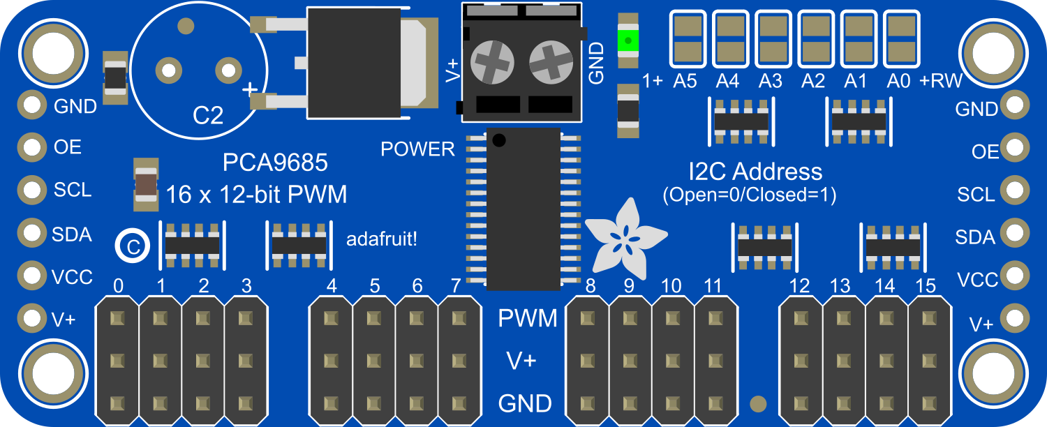
Pin Configuration and Descriptions

Pin Number Pin Name Description
1 VCC Power supply for the PCA9685 and servo motors (5-6V)
2 GND Ground connection
3 SDA I2C data line
4 SCL I2C clock line
5-20 PWM0-15 PWM output channels for servos or LEDs
21 OE Output enable (active low)
22 EXTCLK External clock input (optional)

Usage Instructions

How to Use the Component in a Circuit

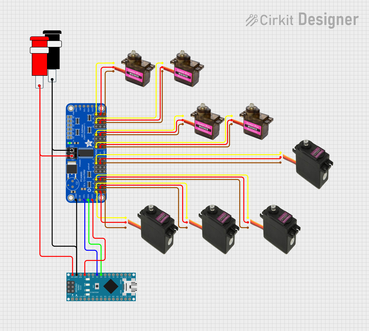
  1. Power Supply: Connect a 5V to 6V power supply to the VCC and GND pins. Ensure that the power supply can handle the current requirements of all connected servos or LEDs.
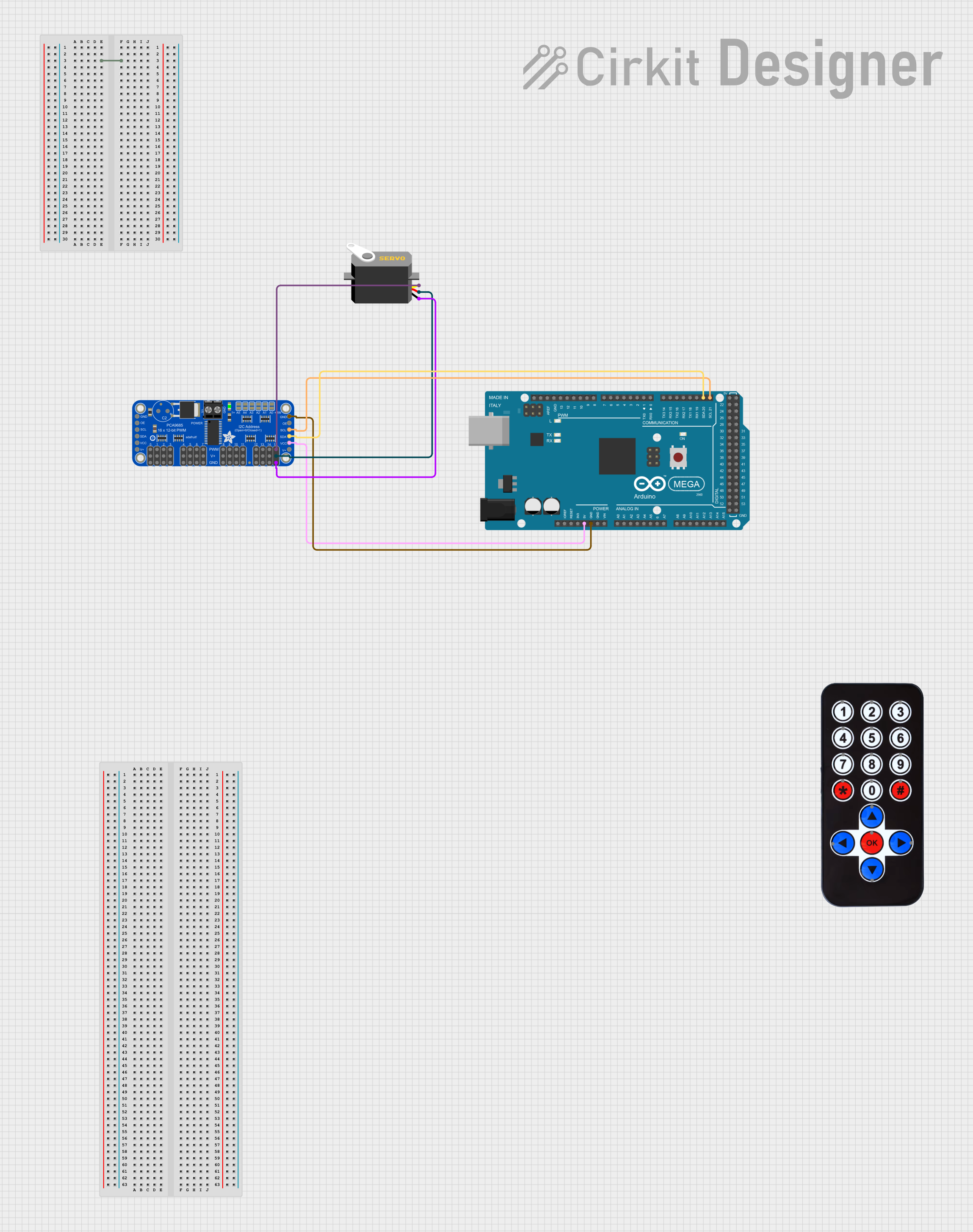
  2. I2C Connection: Connect the SDA and SCL pins to the corresponding I2C pins on your microcontroller.
  3. PWM Outputs: Connect the PWM outputs to your servos or LEDs. Make sure to match the signal, power, and ground wires correctly.
  4. Address Selection: If using multiple PCA9685 boards, set unique I2C addresses using the address jumpers on the board.

Important Considerations and Best Practices

  • Always provide a common ground between the PCA9685 board and the microcontroller.
  • Avoid long wires to reduce noise and potential signal degradation.
  • When driving a large number of servos, ensure the power supply can handle the peak current.
  • Use decoupling capacitors close to the board to stabilize the power supply if necessary.

Example Code for Arduino UNO

#include <Wire.h>
#include <Adafruit_PWMServoDriver.h>

// Called this way, it uses the default address 0x40
Adafruit_PWMServoDriver pwm = Adafruit_PWMServoDriver();

void setup() {
  Serial.begin(9600);
  Serial.println("16 channel PWM test!");

  pwm.begin();
  pwm.setPWMFreq(60);  // Analog servos run at ~60 Hz updates

  delay(10);
}

void loop() {
  // Sweep all servos back and forth
  for (uint16_t pulselen = SERVOMIN; pulselen < SERVOMAX; pulselen++) {
    for (uint8_t i = 0; i < 16; i++) {
      pwm.setPWM(i, 0, pulselen);
    }
  }

  delay(500);
  
  for (uint16_t pulselen = SERVOMAX; pulselen > SERVOMIN; pulselen--) {
    for (uint8_t i = 0; i < 16; i++) {
      pwm.setPWM(i, 0, pulselen);
    }
  }

  delay(500);
}

Note: Before using the above code, define SERVOMIN and SERVOMAX according to the specifications of the servos you are using.

Troubleshooting and FAQs

Common Issues Users Might Face

  • Servos not responding: Check the power supply and wiring. Ensure that the I2C address is correctly set if using multiple PCA9685 boards.
  • Inaccurate servo movement: Calibrate SERVOMIN and SERVOMAX values to match the servo's specifications.
  • LEDs not dimming smoothly: Verify the PWM frequency and ensure it is suitable for the LEDs being used.

Solutions and Tips for Troubleshooting

  • Double-check all connections and ensure that the power supply is adequate.
  • Use the I2C scanner sketch to confirm the PCA9685 is detected on the I2C bus.
  • Review the datasheet of the servos or LEDs to ensure compatibility with the PCA9685's voltage and current specifications.

FAQs

Q: Can I chain multiple PCA9685 boards together? A: Yes, you can connect multiple boards to the same I2C bus by setting a unique address for each board using the address jumpers.

Q: What is the maximum number of servos I can control with one PCA9685 board? A: You can control up to 16 servos per board.

Q: Can I use this board with a Raspberry Pi or other single-board computers? A: Yes, the PCA9685 is compatible with any microcontroller or single-board computer that supports I2C communication.

Q: How do I set a specific PWM frequency? A: Use the setPWMFreq() function in your code to set the desired frequency. The frequency range is 40Hz to 1000Hz.