
How to Use Herelink Air Unit 1.1: Examples, Pinouts, and Specs
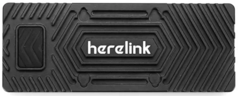
 Design with Herelink Air Unit 1.1 in Cirkit Designer
Introduction
The Herelink Air Unit 1.1, manufactured by CubePilot, is a cutting-edge wireless video transmission system designed specifically for drones and UAVs. It provides high-definition video streaming and low-latency control signals, making it an essential component for real-time monitoring and control of aerial vehicles. This unit is ideal for both recreational drone enthusiasts and professional applications such as aerial photography, surveying, and industrial inspections.
Explore Projects Built with Herelink Air Unit 1.1
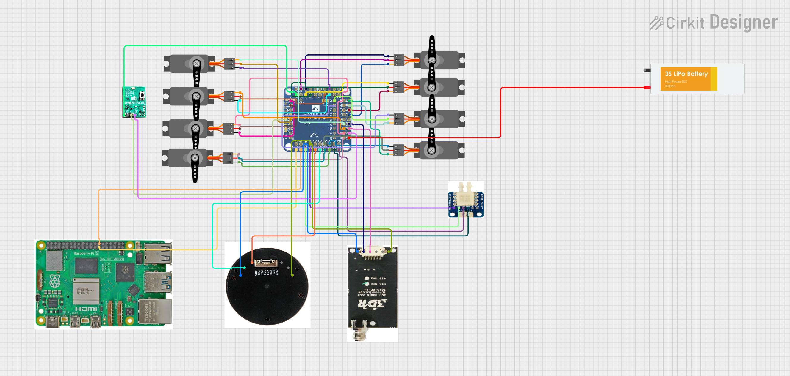 Open Project in Cirkit Designer
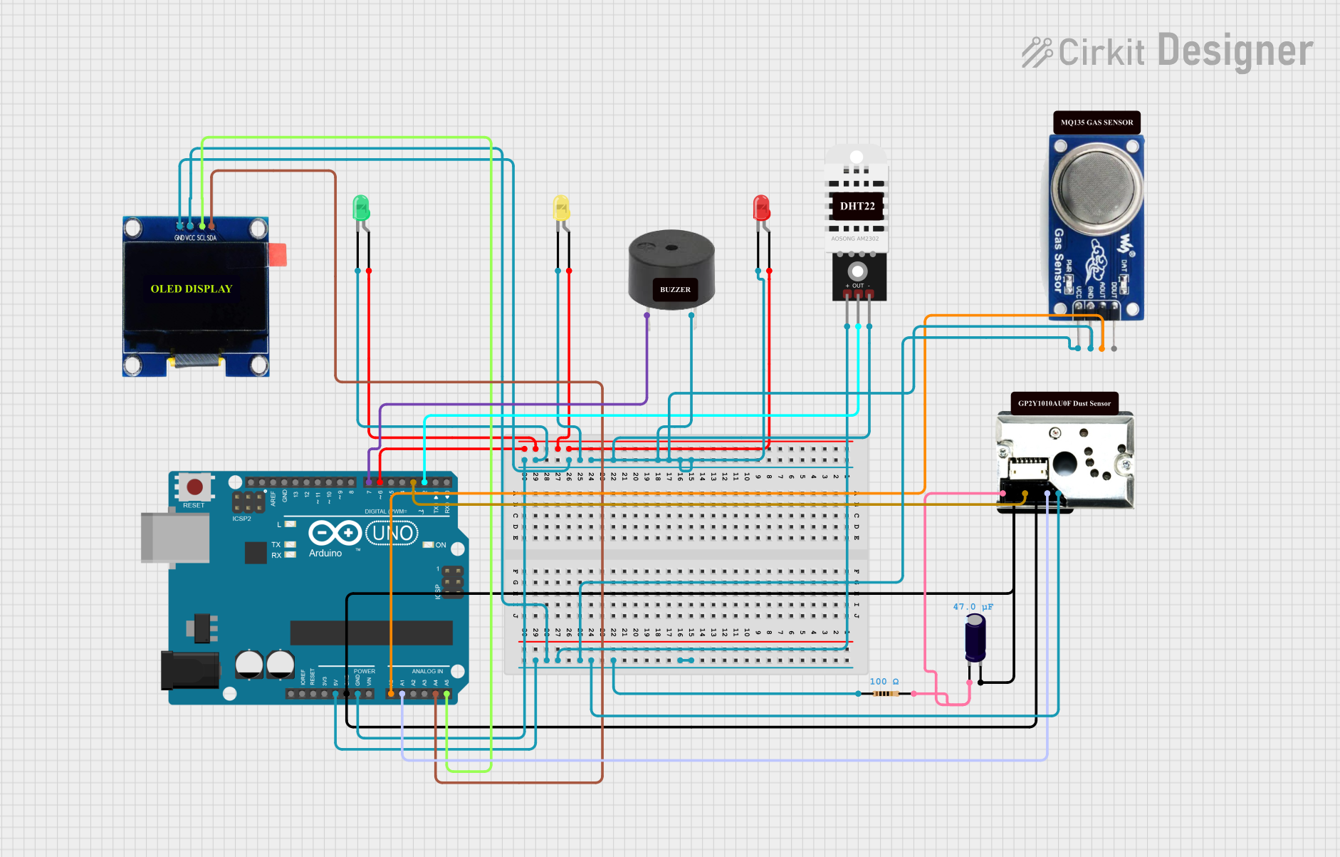 Open Project in Cirkit Designer
 Open Project in Cirkit Designer
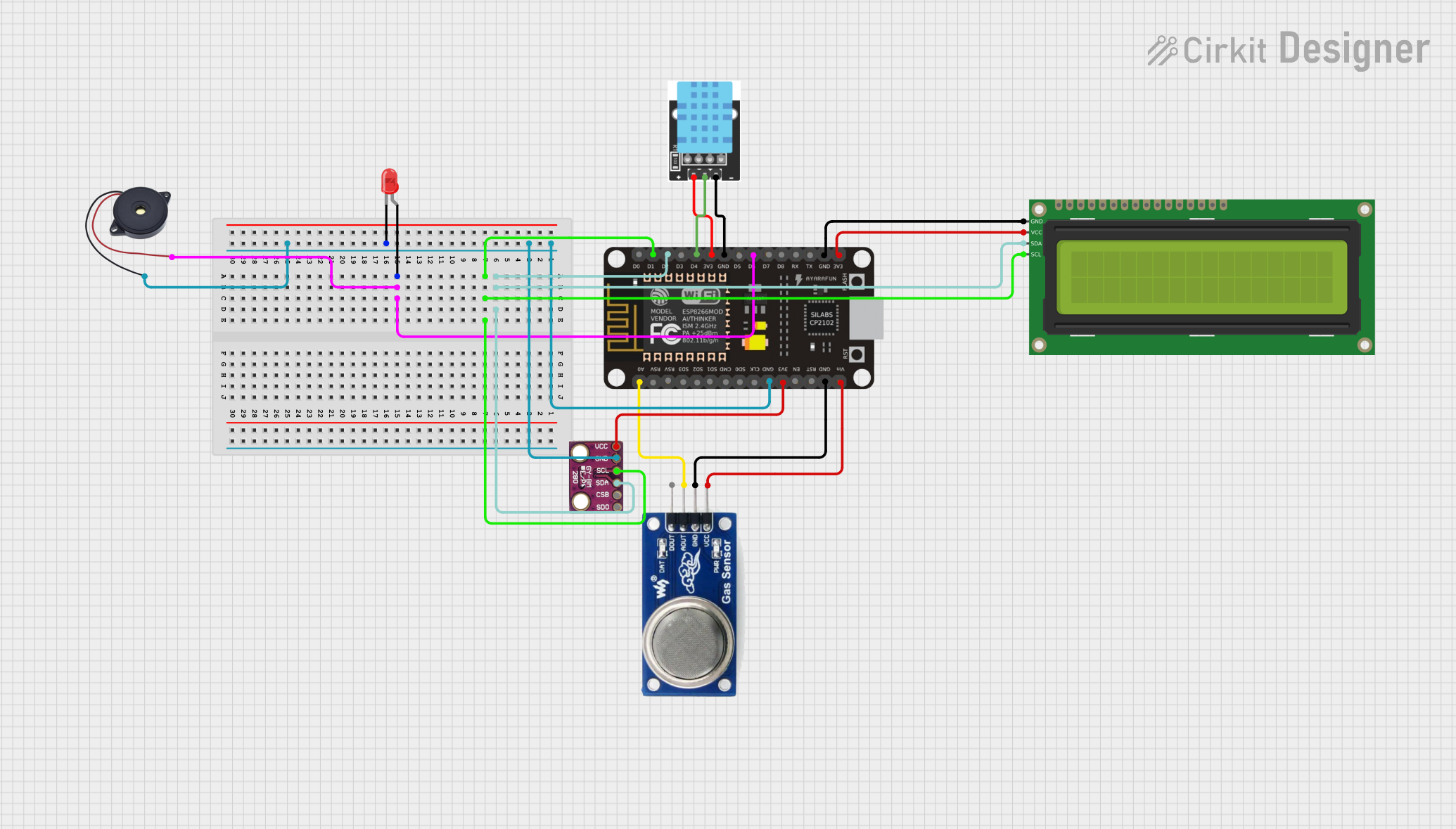 Open Project in Cirkit Designer
Explore Projects Built with Herelink Air Unit 1.1
Open Project in Cirkit DesignerOpen Project in Cirkit DesignerOpen Project in Cirkit DesignerOpen Project in Cirkit DesignerCommon Applications
- Aerial Photography and Videography: Enables high-definition video streaming for capturing stunning visuals.
- Surveying and Mapping: Provides real-time video feedback for precise navigation and data collection.
- Search and Rescue Operations: Facilitates low-latency control and monitoring in critical missions.
- Industrial Inspections: Allows for detailed visual inspections of hard-to-reach areas.
- Recreational Drone Use: Enhances the user experience with seamless video and control capabilities.
Technical Specifications
Key Technical Details
| Parameter | Specification |
|---|---|
| Manufacturer | CubePilot |
| Part ID | Herelink Air Unit |
| Video Resolution | Up to 1080p at 60fps |
| Transmission Range | Up to 20 km (line of sight, depending on environment and antenna configuration) |
| Latency | Less than 110 ms |
| Frequency Band | 2.4 GHz |
| Power Input | 5V DC (via USB-C) |
| Operating Temperature | -10°C to 60°C |
| Dimensions | 90 mm x 60 mm x 20 mm |
| Weight | 120 g |
Pin Configuration and Descriptions
The Herelink Air Unit 1.1 features multiple ports for connectivity. Below is a detailed description of its pin configuration:
| Port Name | Pin/Connector Type | Description |
|---|---|---|
| USB-C Port | USB-C | Power input and firmware updates. |
| HDMI Input | HDMI Type-A | Connects to the camera for high-definition video input. |
| UART Port | JST-GH 6-pin | Serial communication for telemetry and control signals. |
| Antenna Ports | SMA Connectors | Connects to external antennas for wireless transmission. |
| CAN Port | JST-GH 4-pin | CAN bus interface for additional peripherals or communication with flight controllers. |
Usage Instructions
How to Use the Herelink Air Unit 1.1 in a Circuit
Powering the Unit:
- Connect the USB-C port to a 5V DC power source. Ensure the power source can supply sufficient current (minimum 2A).
- Alternatively, power the unit via a compatible drone power distribution board.
Connecting the Camera:
- Use the HDMI input to connect a camera capable of outputting up to 1080p video at 60fps.
- Ensure the HDMI cable is securely connected to avoid signal loss.
Telemetry and Control:
- Connect the UART port to the flight controller for telemetry data and control signals.
- Use the appropriate baud rate as specified by your flight controller's documentation.
Antenna Setup:
- Attach the provided antennas to the SMA connectors. Ensure they are securely fastened for optimal signal transmission.
Pairing with the Ground Unit:
- Power on the Herelink Air Unit and the corresponding ground unit.
- Follow the pairing instructions provided in the CubePilot user manual to establish a connection.
CAN Bus Peripherals:
- If using additional peripherals, connect them to the CAN port. Ensure proper termination and configuration of the CAN bus.
Important Considerations and Best Practices
- Antenna Placement: Position the antennas to minimize interference and maximize signal strength. Avoid placing them near metal objects or other RF sources.
- Firmware Updates: Regularly update the firmware via the USB-C port to ensure compatibility and access to the latest features.
- Environmental Conditions: Operate the unit within the specified temperature range (-10°C to 60°C) to prevent overheating or damage.
- Cable Management: Use high-quality cables and secure connections to avoid accidental disconnections during operation.
Example Code for Arduino UNO Integration
While the Herelink Air Unit is not directly designed for Arduino UNO, it can communicate with an Arduino via the UART port for telemetry purposes. Below is an example code snippet for reading telemetry data:
#include <SoftwareSerial.h>

// Define RX and TX pins for UART communication
SoftwareSerial herelinkSerial(10, 11); // RX = pin 10, TX = pin 11

void setup() {
  // Initialize serial communication
  Serial.begin(9600); // For debugging via Serial Monitor
  herelinkSerial.begin(57600); // Baud rate for Herelink UART communication

  Serial.println("Herelink Air Unit UART Communication Initialized");
}

void loop() {
  // Check if data is available from the Herelink Air Unit
  if (herelinkSerial.available()) {
    String telemetryData = "";

    // Read incoming data
    while (herelinkSerial.available()) {
      telemetryData += (char)herelinkSerial.read();
    }

    // Print telemetry data to Serial Monitor
    Serial.println("Telemetry Data: " + telemetryData);
  }

  delay(100); // Small delay to prevent overwhelming the serial buffer
}
Troubleshooting and FAQs
Common Issues and Solutions
No Video Signal:
- Cause: Loose HDMI connection or incompatible camera.
- Solution: Ensure the HDMI cable is securely connected and the camera supports 1080p output.
High Latency:
- Cause: Interference or poor antenna placement.
- Solution: Reposition the antennas and ensure there are no obstructions or sources of interference nearby.
Connection Drops:
- Cause: Weak signal or improper pairing.
- Solution: Verify the antennas are securely attached and re-pair the Air Unit with the ground unit.
Unit Overheating:
- Cause: Operating in high-temperature environments or insufficient ventilation.
- Solution: Ensure proper airflow around the unit and avoid prolonged use in extreme heat.
FAQs
Q: Can the Herelink Air Unit be used with any flight controller?
- A: Yes, it is compatible with most flight controllers that support UART or CAN communication.
Q: What is the maximum video resolution supported?
- A: The unit supports up to 1080p at 60fps.
Q: How do I update the firmware?
- A: Connect the unit to a computer via the USB-C port and use the CubePilot firmware update tool.
Q: Can I extend the transmission range?
- A: Yes, using high-gain antennas can improve the range, but ensure compliance with local regulations.
This concludes the documentation for the Herelink Air Unit 1.1. For further assistance, refer to the CubePilot user manual or contact their support team.