Cirkit Designer Logo
Cirkit Designer
Your all-in-one circuit design IDE
Home / 
Component Documentation

How to Use MCP4151-502E/P: Examples, Pinouts, and Specs

Image of MCP4151-502E/P
Cirkit Designer LogoDesign with MCP4151-502E/P in Cirkit Designer

Introduction

The MCP4151-502E/P is a digital potentiometer manufactured by Microchip Technology. It features a 5kΩ resistance value with a 256-position wiper, allowing precise control of resistance in analog circuits. The device is controlled via an SPI (Serial Peripheral Interface) communication protocol, making it easy to integrate with microcontrollers and other digital systems.

Explore Projects Built with MCP4151-502E/P

Use Cirkit Designer to design, explore, and prototype these projects online. Some projects support real-time simulation. Click "Open Project" to start designing instantly!
STM32 and ESP32 CAN Bus Communication System with MCP2515
Image of CAR HACKING: A project utilizing MCP4151-502E/P in a practical application
This circuit integrates multiple microcontrollers (STM32F103C8T6, ESP32, and Raspberry Pi Pico W) with MCP2515 CAN controllers to facilitate CAN bus communication. The microcontrollers are connected to the MCP2515 modules via SPI interfaces, and the circuit includes USB-to-serial converters for programming and debugging purposes.
Cirkit Designer LogoOpen Project in Cirkit Designer
Battery-Powered Raspberry Pi Pico GPS Tracker with Sensor Integration
Image of Copy of CanSet v1: A project utilizing MCP4151-502E/P in a practical application
This circuit is a data acquisition and communication system powered by a LiPoly battery and managed by a Raspberry Pi Pico. It includes sensors (BMP280, MPU9250) for environmental data, a GPS module for location tracking, an SD card for data storage, and a WLR089-CanSAT for wireless communication. The TP4056 module handles battery charging, and a toggle switch controls power distribution.
Cirkit Designer LogoOpen Project in Cirkit Designer
ESP32-C3 Mini and MCP4725 DAC Controlled Analog Output Circuit
Image of pp: A project utilizing MCP4151-502E/P in a practical application
This circuit features an ESP32-C3 Mini microcontroller that interfaces with an Adafruit MCP4725 DAC via I2C for analog output, which is then fed into an OPA2333 operational amplifier. Power management is handled by a 5V step-down voltage regulator that receives power from a 2000mAh battery and supplies the ESP32-C3 and a 3.3V AMS1117 voltage regulator. Additionally, the circuit includes user input through buttons and electro pads, with debouncing provided by resistors.
Cirkit Designer LogoOpen Project in Cirkit Designer
Biometric and RFID Security System with Dual Adafruit Feather nRF52840 Controllers
Image of Rfid access control: A project utilizing MCP4151-502E/P in a practical application
This circuit features two Adafruit Feather nRF52840 microcontrollers, each interfaced with an RFID-RC522 module for RFID communication and an AT24C256 external EEPROM for additional memory storage. One of the microcontrollers is also connected to an R307 Fingerprint Sensor for biometric input, and both microcontrollers are powered by a shared power supply and a coin cell breakout for backup or RTC power. The circuit is likely designed for secure access control or identification purposes, utilizing both RFID and fingerprint authentication, with data storage capabilities.
Cirkit Designer LogoOpen Project in Cirkit Designer

Explore Projects Built with MCP4151-502E/P

Use Cirkit Designer to design, explore, and prototype these projects online. Some projects support real-time simulation. Click "Open Project" to start designing instantly!
Image of CAR HACKING: A project utilizing MCP4151-502E/P in a practical application
STM32 and ESP32 CAN Bus Communication System with MCP2515
This circuit integrates multiple microcontrollers (STM32F103C8T6, ESP32, and Raspberry Pi Pico W) with MCP2515 CAN controllers to facilitate CAN bus communication. The microcontrollers are connected to the MCP2515 modules via SPI interfaces, and the circuit includes USB-to-serial converters for programming and debugging purposes.
Cirkit Designer LogoOpen Project in Cirkit Designer
Image of Copy of CanSet v1: A project utilizing MCP4151-502E/P in a practical application
Battery-Powered Raspberry Pi Pico GPS Tracker with Sensor Integration
This circuit is a data acquisition and communication system powered by a LiPoly battery and managed by a Raspberry Pi Pico. It includes sensors (BMP280, MPU9250) for environmental data, a GPS module for location tracking, an SD card for data storage, and a WLR089-CanSAT for wireless communication. The TP4056 module handles battery charging, and a toggle switch controls power distribution.
Cirkit Designer LogoOpen Project in Cirkit Designer
Image of pp: A project utilizing MCP4151-502E/P in a practical application
ESP32-C3 Mini and MCP4725 DAC Controlled Analog Output Circuit
This circuit features an ESP32-C3 Mini microcontroller that interfaces with an Adafruit MCP4725 DAC via I2C for analog output, which is then fed into an OPA2333 operational amplifier. Power management is handled by a 5V step-down voltage regulator that receives power from a 2000mAh battery and supplies the ESP32-C3 and a 3.3V AMS1117 voltage regulator. Additionally, the circuit includes user input through buttons and electro pads, with debouncing provided by resistors.
Cirkit Designer LogoOpen Project in Cirkit Designer
Image of Rfid access control: A project utilizing MCP4151-502E/P in a practical application
Biometric and RFID Security System with Dual Adafruit Feather nRF52840 Controllers
This circuit features two Adafruit Feather nRF52840 microcontrollers, each interfaced with an RFID-RC522 module for RFID communication and an AT24C256 external EEPROM for additional memory storage. One of the microcontrollers is also connected to an R307 Fingerprint Sensor for biometric input, and both microcontrollers are powered by a shared power supply and a coin cell breakout for backup or RTC power. The circuit is likely designed for secure access control or identification purposes, utilizing both RFID and fingerprint authentication, with data storage capabilities.
Cirkit Designer LogoOpen Project in Cirkit Designer

Common Applications and Use Cases

  • Volume control in audio systems
  • Adjustable gain in amplifiers
  • Calibration and trimming in sensor circuits
  • Programmable voltage dividers
  • LED dimming and brightness control
  • Resistance tuning in test and measurement equipment

Technical Specifications

The following table outlines the key technical details of the MCP4151-502E/P:

Parameter Value
Resistance Value 5kΩ
Number of Wiper Positions 256
Communication Interface SPI
Supply Voltage (VDD) 2.7V to 5.5V
Wiper Resistance (Typical) 75Ω
Operating Temperature Range -40°C to +125°C
End-to-End Resistance Tolerance ±20%
Maximum Current (through resistor) ±2.5mA
Package Type PDIP-8

Pin Configuration and Descriptions

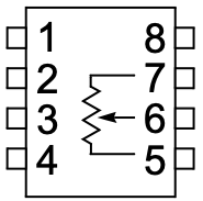
The MCP4151-502E/P is available in an 8-pin PDIP package. The pinout and descriptions are as follows:

Pin Number Pin Name Description
1 CS Chip Select (Active Low). Enables SPI communication when pulled low.
2 SCK Serial Clock Input. Used to synchronize data transfer in SPI communication.
3 SI Serial Data Input. Receives data from the microcontroller.
4 VSS Ground (0V reference).
5 PW0 Terminal 0 of the potentiometer.
6 PW1 Terminal 1 of the potentiometer.
7 VW Wiper terminal. Provides the adjustable resistance output.
8 VDD Positive supply voltage (2.7V to 5.5V).

Usage Instructions

How to Use the MCP4151-502E/P in a Circuit

  1. Power Supply: Connect the VDD pin to a stable power source (2.7V to 5.5V) and the VSS pin to ground.
  2. SPI Connections:
    • Connect the CS, SCK, and SI pins to the corresponding SPI pins on your microcontroller.
    • Ensure proper pull-up or pull-down resistors if required by your system.
  3. Potentiometer Terminals:
    • Connect PW0 and PW1 to the circuit where the resistance is needed.
    • The adjustable resistance is available between VW (wiper) and either PW0 or PW1.
  4. SPI Communication:
    • Use SPI commands to set the wiper position (0 to 255). Each step corresponds to approximately 19.6Ω (5kΩ ÷ 256).

Important Considerations and Best Practices

  • Power Supply Stability: Ensure a clean and stable power supply to avoid noise in the resistance adjustment.
  • Wiper Current: Avoid exceeding the maximum wiper current of ±2.5mA to prevent damage to the device.
  • SPI Timing: Follow the SPI timing requirements specified in the datasheet for reliable communication.
  • Unused Pins: Leave unused potentiometer terminals (PW0 or PW1) floating if not connected in the circuit.

Example: Using MCP4151-502E/P with Arduino UNO

Below is an example of how to control the MCP4151-502E/P using an Arduino UNO:

#include <SPI.h>

// Define SPI pins for MCP4151
const int CS_PIN = 10; // Chip Select pin connected to Arduino pin 10

void setup() {
  pinMode(CS_PIN, OUTPUT); // Set CS pin as output
  digitalWrite(CS_PIN, HIGH); // Set CS pin high (inactive)

  SPI.begin(); // Initialize SPI communication
  SPI.setClockDivider(SPI_CLOCK_DIV16); // Set SPI clock speed
  SPI.setDataMode(SPI_MODE0); // Set SPI mode (Mode 0)
}

void loop() {
  setWiperPosition(128); // Set wiper to mid-position (50% of 5kΩ)
  delay(1000); // Wait for 1 second
  setWiperPosition(255); // Set wiper to maximum position (5kΩ)
  delay(1000); // Wait for 1 second
}

// Function to set the wiper position (0 to 255)
void setWiperPosition(byte position) {
  digitalWrite(CS_PIN, LOW); // Activate the MCP4151 by pulling CS low
  SPI.transfer(0x00); // Send command byte (write to wiper register)
  SPI.transfer(position); // Send the wiper position (0-255)
  digitalWrite(CS_PIN, HIGH); // Deactivate the MCP4151 by pulling CS high
}

Notes:

  • The setWiperPosition function sends two bytes over SPI: a command byte and the wiper position.
  • Adjust the CS_PIN definition if using a different pin for Chip Select.

Troubleshooting and FAQs

Common Issues and Solutions

  1. No Response from MCP4151:

    • Ensure the CS pin is pulled low during SPI communication.
    • Verify the SPI clock speed and mode match the MCP4151 requirements.
  2. Incorrect Resistance Output:

    • Check the wiper position value being sent (0 to 255).
    • Verify the connections to the potentiometer terminals (PW0, PW1, and VW).
  3. Device Overheating:

    • Ensure the wiper current does not exceed ±2.5mA.
    • Verify the supply voltage is within the 2.7V to 5.5V range.
  4. SPI Communication Errors:

    • Check for loose or incorrect connections between the microcontroller and MCP4151.
    • Ensure proper grounding between all components in the circuit.

FAQs

Q: Can the MCP4151-502E/P be used with 3.3V systems?
A: Yes, the MCP4151 operates with supply voltages as low as 2.7V, making it compatible with 3.3V systems.

Q: What happens if the wiper current exceeds the maximum rating?
A: Exceeding the maximum wiper current of ±2.5mA can damage the internal circuitry of the MCP4151.

Q: Can I use the MCP4151 to control AC signals?
A: The MCP4151 is designed for DC applications. Using it with AC signals may result in unpredictable behavior or damage.

Q: How precise is the resistance adjustment?
A: The MCP4151 provides 256 discrete wiper positions, with each step corresponding to approximately 19.6Ω for the 5kΩ version.