How to Use RFID-RC522: Examples, Pinouts, and Specs
Introduction
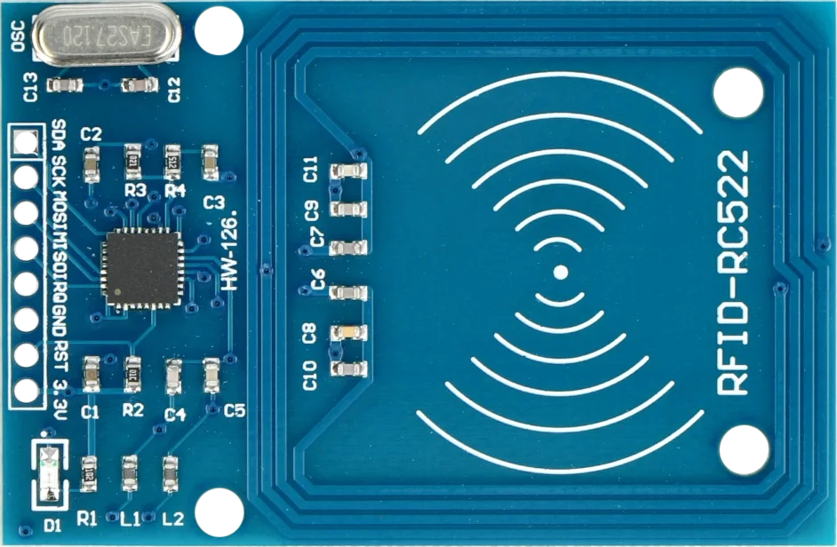
The RFID-RC522 is a popular RFID (Radio Frequency Identification) module that operates at 13.56 MHz. It is widely used for contactless communication and is capable of reading and writing to various RFID tags and cards. This module is commonly utilized in applications such as access control systems, attendance systems, and identification tasks where a secure and quick method of data exchange is required.
Explore Projects Built with RFID-RC522
Explore Projects Built with RFID-RC522
Technical Specifications
Key Technical Details
- Frequency: 13.56 MHz
- Supply Voltage: 2.5V to 3.3V
- Current Consumption: 13-26mA (operating); 10uA (sleep mode)
- Supported Card Types: Mifare1 S50, Mifare1 S70, Mifare UltraLight, Mifare Pro, Mifare Desfire
- Operating Distance: Up to 50mm (depending on antenna geometry)
- Interface: SPI
- Data Transfer Rate: Max. 10 Mbit/s
Pin Configuration and Descriptions
| Pin Name | Description |
|---|---|
| SDA | Serial Data Signal (SPI SS) |
| SCK | Serial Clock Signal (SPI SCK) |
| MOSI | Master Out Slave In (SPI MOSI) |
| MISO | Master In Slave Out (SPI MISO) |
| IRQ | Interrupt Request (active low) |
| GND | Ground |
| RST | Reset Signal |
| 3.3V | Supply Voltage (3.3V) |
Usage Instructions
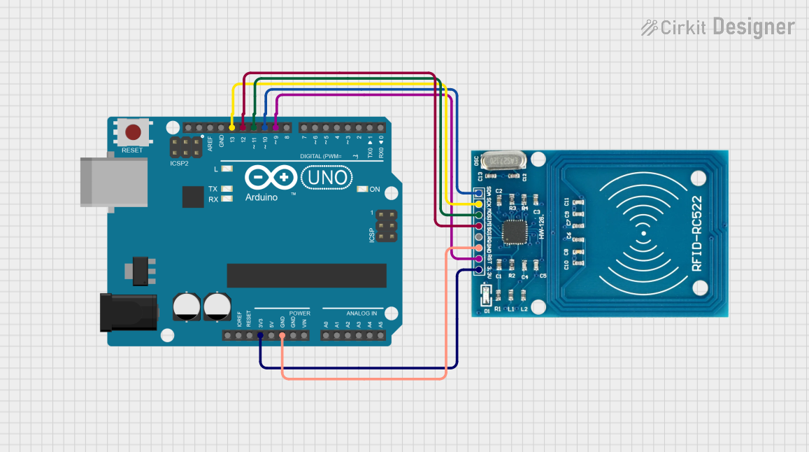
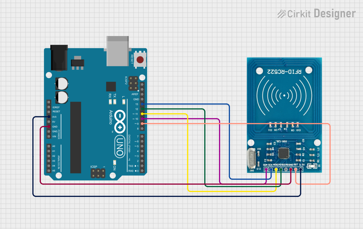
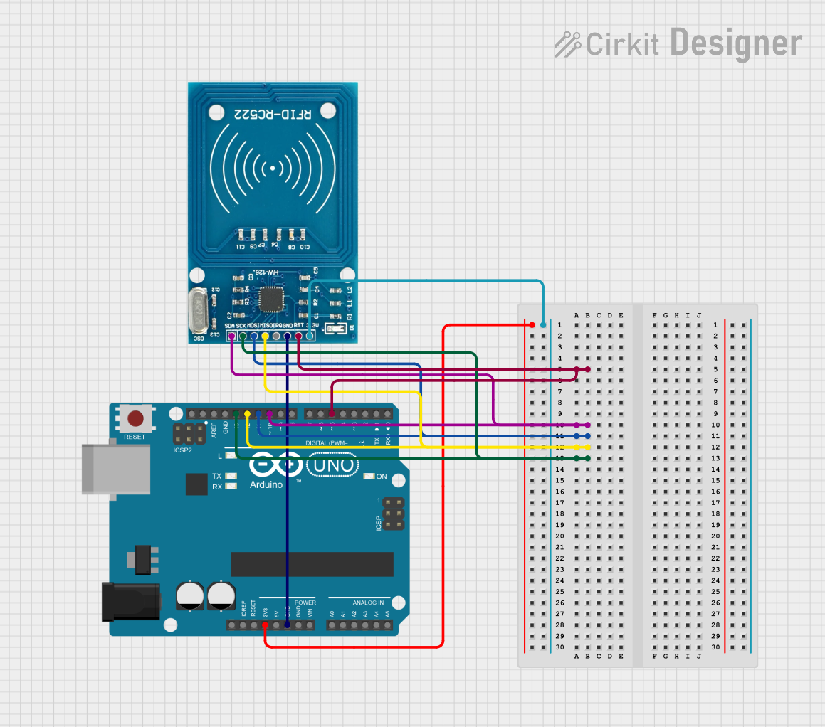
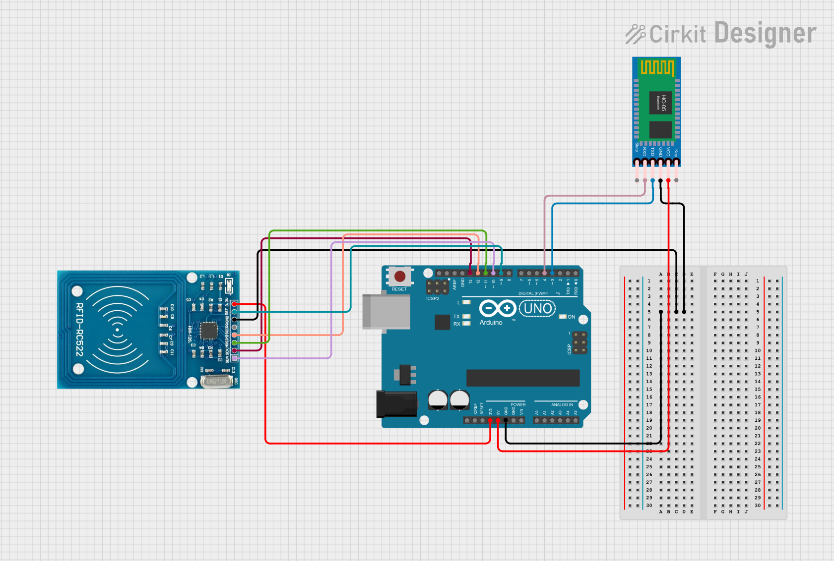
Integration with a Circuit
To use the RFID-RC522 module in a circuit, follow these steps:
- Connect the module's power pins (3.3V and GND) to the power supply of your microcontroller, ensuring that it is within the specified voltage range.
- Interface the SPI pins (SDA, SCK, MOSI, MISO) with the corresponding SPI pins on your microcontroller.
- Optionally, connect the RST pin to a digital pin on your microcontroller to control the reset function.
- The IRQ pin can be left unconnected if interrupt-driven operation is not required.
Important Considerations and Best Practices
- Ensure that the power supply is stable and within the specified voltage range to prevent damage to the module.
- Place the RFID-RC522 module away from metal surfaces as they can interfere with the RF field.
- For reliable communication, maintain a clear line of sight between the RFID tag/card and the module's antenna.
- Use proper decoupling capacitors close to the module's power pins to filter out noise and voltage spikes.
Example Code for Arduino UNO
#include <SPI.h>
#include <MFRC522.h>

#define SS_PIN 10
#define RST_PIN 9
MFRC522 mfrc522(SS_PIN, RST_PIN); // Create MFRC522 instance

void setup() {
  Serial.begin(9600); // Initialize serial communications with the PC
  SPI.begin();        // Init SPI bus
  mfrc522.PCD_Init(); // Init MFRC522 card
  Serial.println("Scan a MIFARE Classic card");
}

void loop() {
  // Look for new cards
  if (!mfrc522.PICC_IsNewCardPresent() || !mfrc522.PICC_ReadCardSerial()) {
    delay(50);
    return;
  }

  // Show UID on serial monitor
  Serial.print("Card UID:");
  for (byte i = 0; i < mfrc522.uid.size; i++) {
    Serial.print(mfrc522.uid.uidByte[i] < 0x10 ? " 0" : " ");
    Serial.print(mfrc522.uid.uidByte[i], HEX);
  }
  Serial.println();

  // Halt PICC
  mfrc522.PICC_HaltA();
  // Stop encryption on PCD
  mfrc522.PCD_StopCrypto1();
}
Troubleshooting and FAQs
Common Issues
- Tag Read Failure: Ensure the tag is within the operational range and the antenna is not obstructed by metal objects.
- Communication Errors: Check the wiring and connections between the RFID-RC522 module and the microcontroller.
- Module Not Powering Up: Verify the power supply is within the specified voltage range and properly connected.
Solutions and Tips for Troubleshooting
- If the module is not responding, try resetting the microcontroller and the RFID-RC522 module.
- Ensure that the SPI bus is not shared with other devices that might interfere with the communication.
- Check for soldering issues on the module pins and re-solder if necessary.
- Use the example code provided to test basic functionality before integrating the module into a larger system.
FAQs
Q: Can the RFID-RC522 module write to RFID tags? A: Yes, the RFID-RC522 can write to compatible RFID tags that support the MIFARE protocol.
Q: What is the maximum range of the RFID-RC522 module? A: The maximum range is approximately 50mm, but this can vary based on the antenna design and environmental conditions.
Q: Is the RFID-RC522 module compatible with all RFID tags? A: No, it is designed to work with tags that operate at 13.56 MHz and support the MIFARE protocol.
Q: Can I use the RFID-RC522 module with a 5V microcontroller? A: While the module itself requires 3.3V, level shifters can be used to interface with 5V logic levels on a microcontroller. However, direct connection without level shifting can damage the module.