
How to Use MCB 3P: Examples, Pinouts, and Specs
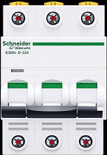
 Design with MCB 3P in Cirkit Designer
Introduction
The MCB 3P (Miniature Circuit Breaker, 3-pole) by Sch is a compact and reliable device designed to protect electrical circuits from overloads and short circuits. It automatically disconnects the circuit when a fault is detected, ensuring the safety of electrical systems and connected devices. This 3-pole MCB is specifically designed for three-phase systems, making it ideal for industrial, commercial, and residential applications.
Explore Projects Built with MCB 3P
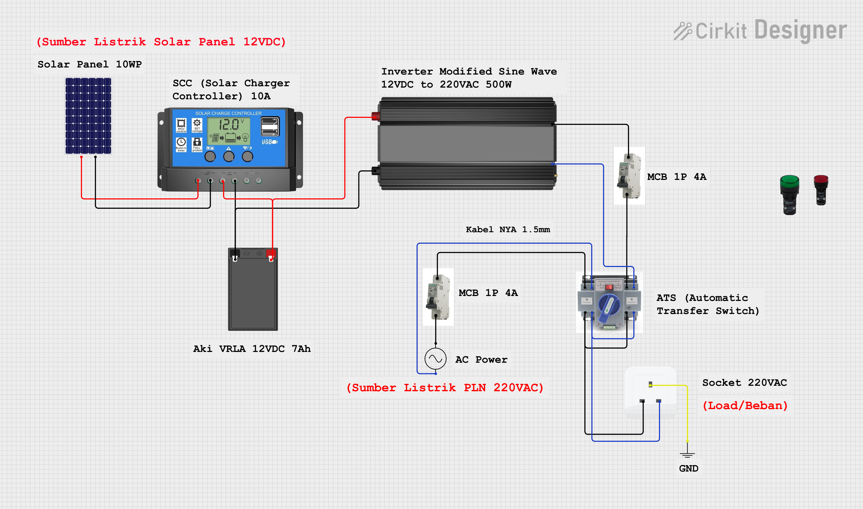 Open Project in Cirkit Designer
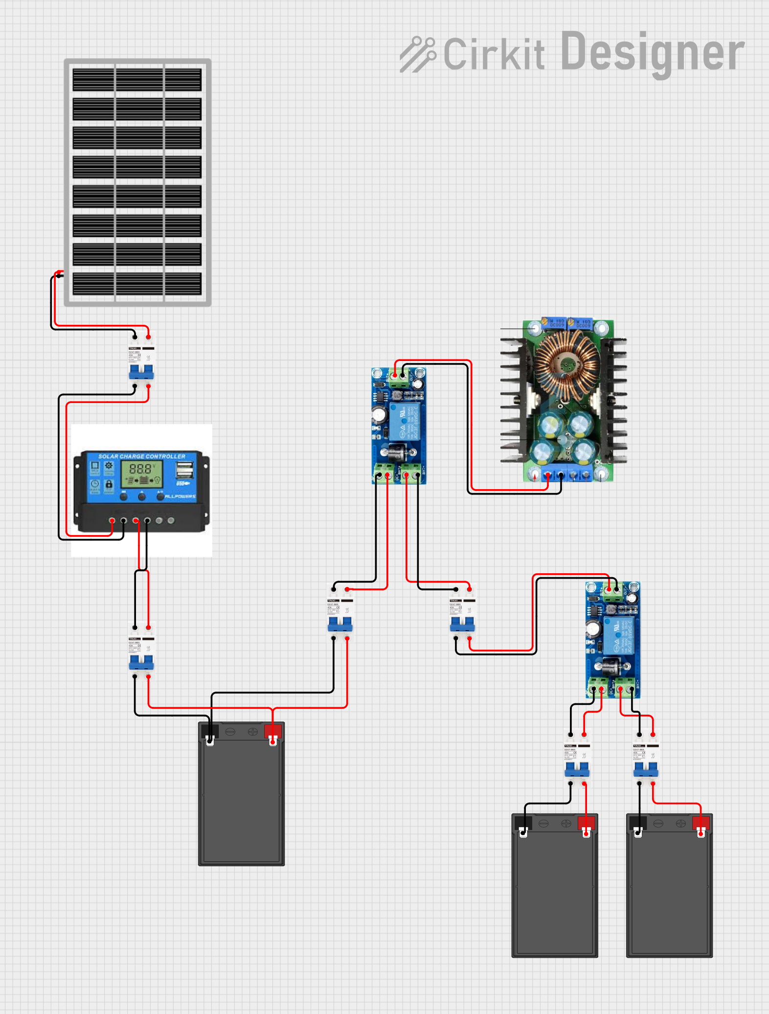 Open Project in Cirkit Designer
 Open Project in Cirkit Designer
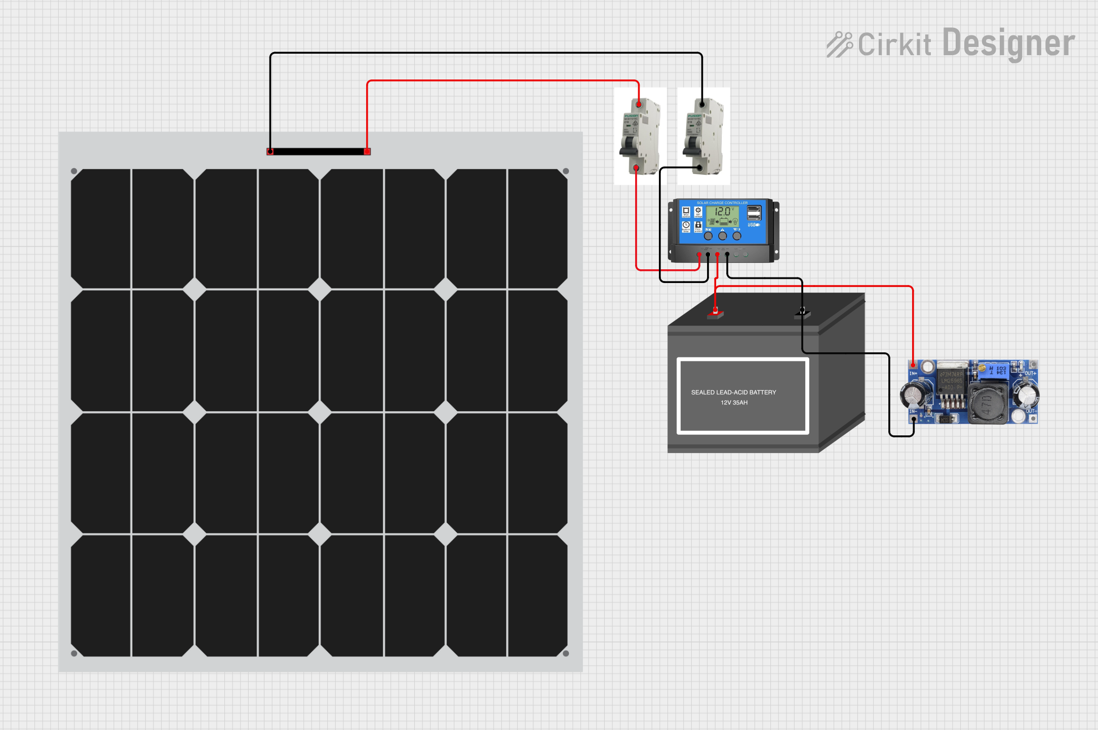 Open Project in Cirkit Designer
Explore Projects Built with MCB 3P
Open Project in Cirkit DesignerOpen Project in Cirkit DesignerOpen Project in Cirkit DesignerOpen Project in Cirkit DesignerCommon Applications and Use Cases
- Protection of three-phase electrical systems in industrial environments.
- Safeguarding commercial electrical installations from overloads and short circuits.
- Residential use in three-phase power distribution systems.
- Use in motor protection circuits and other high-power applications.
Technical Specifications
The following table outlines the key technical details of the MCB 3P:
| Parameter | Specification |
|---|---|
| Manufacturer | Sch |
| Number of Poles | 3 |
| Rated Voltage | 400V AC |
| Rated Current | 6A, 10A, 16A, 20A, 32A, 40A, 63A |
| Breaking Capacity | 6kA or 10kA (depending on model) |
| Tripping Curve | B, C, or D (based on application) |
| Frequency | 50/60 Hz |
| Operating Temperature | -5°C to +40°C |
| Mounting Type | DIN Rail |
| Standards Compliance | IEC/EN 60898-1 |
Pin Configuration and Descriptions
The MCB 3P does not have traditional pins but instead features terminal connections for three-phase wiring. The table below describes the terminal connections:
| Terminal Label | Description |
|---|---|
| L1 | Input for Phase 1 (Line 1) |
| L2 | Input for Phase 2 (Line 2) |
| L3 | Input for Phase 3 (Line 3) |
| OUT1 | Output for Phase 1 (connected load) |
| OUT2 | Output for Phase 2 (connected load) |
| OUT3 | Output for Phase 3 (connected load) |
Usage Instructions
How to Use the MCB 3P in a Circuit
Mounting the MCB:
- Install the MCB on a standard DIN rail in the distribution box or panel.
- Ensure the MCB is securely locked into place to prevent movement during operation.
Wiring the MCB:
- Connect the three-phase input lines (L1, L2, L3) to the corresponding input terminals of the MCB.
- Connect the output terminals (OUT1, OUT2, OUT3) to the load or downstream circuit.
- Tighten all terminal screws to ensure a secure connection.
Powering On:
- After verifying all connections, switch the MCB to the "ON" position to energize the circuit.
- The MCB will automatically trip to the "OFF" position if an overload or short circuit occurs.
Important Considerations and Best Practices
- Select the Correct Rating: Choose an MCB with the appropriate current rating and tripping curve (B, C, or D) based on the load and application.
- Avoid Overloading: Ensure the connected load does not exceed the rated current of the MCB.
- Regular Maintenance: Periodically inspect the MCB for signs of wear, loose connections, or damage.
- Proper Grounding: Ensure the electrical system is properly grounded to enhance safety and reduce the risk of electrical faults.
Example: Connecting the MCB 3P to an Arduino-Controlled System
While the MCB 3P is not directly interfaced with microcontrollers like Arduino, it can be used in conjunction with an Arduino-based system to protect the power supply. For example, you can use the MCB to safeguard a three-phase motor controlled by an Arduino.
// Example: Controlling a three-phase motor with Arduino
// Note: The MCB 3P is used to protect the motor circuit, not directly controlled by Arduino.

const int motorControlPin = 9; // Pin to control motor relay

void setup() {
  pinMode(motorControlPin, OUTPUT); // Set motor control pin as output
  digitalWrite(motorControlPin, LOW); // Ensure motor is off at startup
}

void loop() {
  // Example: Turn motor on for 5 seconds, then off for 5 seconds
  digitalWrite(motorControlPin, HIGH); // Turn motor on
  delay(5000); // Wait for 5 seconds
  digitalWrite(motorControlPin, LOW); // Turn motor off
  delay(5000); // Wait for 5 seconds
}

// Note: Ensure the MCB 3P is installed between the power source and the motor
// to protect the circuit from overloads or short circuits.
Troubleshooting and FAQs
Common Issues and Solutions
| Issue | Possible Cause | Solution |
|---|---|---|
| MCB trips frequently | Overloaded circuit | Reduce the load or use an MCB with a higher current rating. |
| MCB does not trip during faults | Faulty MCB or incorrect wiring | Inspect wiring and replace the MCB if necessary. |
| MCB does not switch on | Loose connections or damaged terminals | Check and tighten connections; replace damaged parts. |
FAQs
Can the MCB 3P be used for single-phase systems?
Yes, but it is designed for three-phase systems. For single-phase systems, a single-pole or double-pole MCB is more suitable.What is the difference between B, C, and D tripping curves?
- B Curve: Trips at 3-5 times the rated current, suitable for resistive loads.
- C Curve: Trips at 5-10 times the rated current, ideal for inductive loads like motors.
- D Curve: Trips at 10-20 times the rated current, used for high inrush current loads.
How do I select the correct MCB rating?
Calculate the total load current and choose an MCB with a slightly higher rated current. Consider the type of load and select the appropriate tripping curve.
By following this documentation, users can effectively install, use, and troubleshoot the MCB 3P to ensure safe and reliable operation in their electrical systems.