Cirkit Designer Logo
Cirkit Designer
Your all-in-one circuit design IDE
Home / 
Component Documentation

How to Use Adafruit LiPoly Backpack: Examples, Pinouts, and Specs

Image of Adafruit LiPoly Backpack
Cirkit Designer LogoDesign with Adafruit LiPoly Backpack in Cirkit Designer

Introduction

The Adafruit LiPoly Backpack is an essential component for hobbyists and professionals looking to integrate a rechargeable power source into their projects. This compact module not only provides a charging solution for lithium polymer (LiPo) batteries but also includes protection circuitry and a power supply option via a USB port. It is commonly used in portable electronics, wearables, and IoT devices where a reliable and rechargeable power source is required.

Explore Projects Built with Adafruit LiPoly Backpack

Use Cirkit Designer to design, explore, and prototype these projects online. Some projects support real-time simulation. Click "Open Project" to start designing instantly!
Battery-Powered Raspberry Pi Pico GPS and Sensor Data Logger
Image of CanSet v1: A project utilizing Adafruit LiPoly Backpack in a practical application
This circuit is a data logging and telemetry system powered by a LiPoly battery and managed by a Raspberry Pi Pico. It includes sensors for environmental data (BMP280 for pressure and temperature, MPU9250 for motion), a GPS module for location tracking, and an SD card for data storage, with a TP4056 module for battery charging and a toggle switch for power control.
Cirkit Designer LogoOpen Project in Cirkit Designer
Battery-Powered Raspberry Pi Pico GPS Tracker with Sensor Integration
Image of Copy of CanSet v1: A project utilizing Adafruit LiPoly Backpack in a practical application
This circuit is a data acquisition and communication system powered by a LiPoly battery and managed by a Raspberry Pi Pico. It includes sensors (BMP280, MPU9250) for environmental data, a GPS module for location tracking, an SD card for data storage, and a WLR089-CanSAT for wireless communication. The TP4056 module handles battery charging, and a toggle switch controls power distribution.
Cirkit Designer LogoOpen Project in Cirkit Designer
Battery-Powered Smart Light with Proximity Sensor and OLED Display using Adafruit QT Py RP2040
Image of lab: A project utilizing Adafruit LiPoly Backpack in a practical application
This circuit is a portable, battery-powered system featuring an Adafruit QT Py RP2040 microcontroller that interfaces with an OLED display, a proximity sensor, an accelerometer, and an RGB LED strip. The system is powered by a lithium-ion battery with a step-up boost converter to provide 5V for the LED strip, and it includes a toggle switch for power control. The microcontroller communicates with the sensors and display via I2C.
Cirkit Designer LogoOpen Project in Cirkit Designer
Battery-Powered Sensor Hub with Adafruit QT Py RP2040 and OLED Display
Image of 512: A project utilizing Adafruit LiPoly Backpack in a practical application
This circuit features an Adafruit QT Py RP2040 microcontroller interfacing with an MPU-6050 accelerometer, an Adafruit APDS-9960 sensor, and a 0.96" OLED display via I2C communication. It is powered by a 3.7V LiPo battery and includes a green LED with a current-limiting resistor connected to an analog pin of the microcontroller.
Cirkit Designer LogoOpen Project in Cirkit Designer

Explore Projects Built with Adafruit LiPoly Backpack

Use Cirkit Designer to design, explore, and prototype these projects online. Some projects support real-time simulation. Click "Open Project" to start designing instantly!
Image of CanSet v1: A project utilizing Adafruit LiPoly Backpack in a practical application
Battery-Powered Raspberry Pi Pico GPS and Sensor Data Logger
This circuit is a data logging and telemetry system powered by a LiPoly battery and managed by a Raspberry Pi Pico. It includes sensors for environmental data (BMP280 for pressure and temperature, MPU9250 for motion), a GPS module for location tracking, and an SD card for data storage, with a TP4056 module for battery charging and a toggle switch for power control.
Cirkit Designer LogoOpen Project in Cirkit Designer
Image of Copy of CanSet v1: A project utilizing Adafruit LiPoly Backpack in a practical application
Battery-Powered Raspberry Pi Pico GPS Tracker with Sensor Integration
This circuit is a data acquisition and communication system powered by a LiPoly battery and managed by a Raspberry Pi Pico. It includes sensors (BMP280, MPU9250) for environmental data, a GPS module for location tracking, an SD card for data storage, and a WLR089-CanSAT for wireless communication. The TP4056 module handles battery charging, and a toggle switch controls power distribution.
Cirkit Designer LogoOpen Project in Cirkit Designer
Image of lab: A project utilizing Adafruit LiPoly Backpack in a practical application
Battery-Powered Smart Light with Proximity Sensor and OLED Display using Adafruit QT Py RP2040
This circuit is a portable, battery-powered system featuring an Adafruit QT Py RP2040 microcontroller that interfaces with an OLED display, a proximity sensor, an accelerometer, and an RGB LED strip. The system is powered by a lithium-ion battery with a step-up boost converter to provide 5V for the LED strip, and it includes a toggle switch for power control. The microcontroller communicates with the sensors and display via I2C.
Cirkit Designer LogoOpen Project in Cirkit Designer
Image of 512: A project utilizing Adafruit LiPoly Backpack in a practical application
Battery-Powered Sensor Hub with Adafruit QT Py RP2040 and OLED Display
This circuit features an Adafruit QT Py RP2040 microcontroller interfacing with an MPU-6050 accelerometer, an Adafruit APDS-9960 sensor, and a 0.96" OLED display via I2C communication. It is powered by a 3.7V LiPo battery and includes a green LED with a current-limiting resistor connected to an analog pin of the microcontroller.
Cirkit Designer LogoOpen Project in Cirkit Designer

Technical Specifications

Key Technical Details

  • Input Voltage (for charging): 5V via micro USB
  • Battery Voltage: 3.7V nominal (for standard LiPo batteries)
  • Charge Current: 100mA by default, adjustable up to 500mA
  • Output Voltage: 3.7V to 5V (boost converter output)
  • Maximum Output Current: 500mA (depends on battery capacity)
  • Protection: Overcharge and over-discharge protection

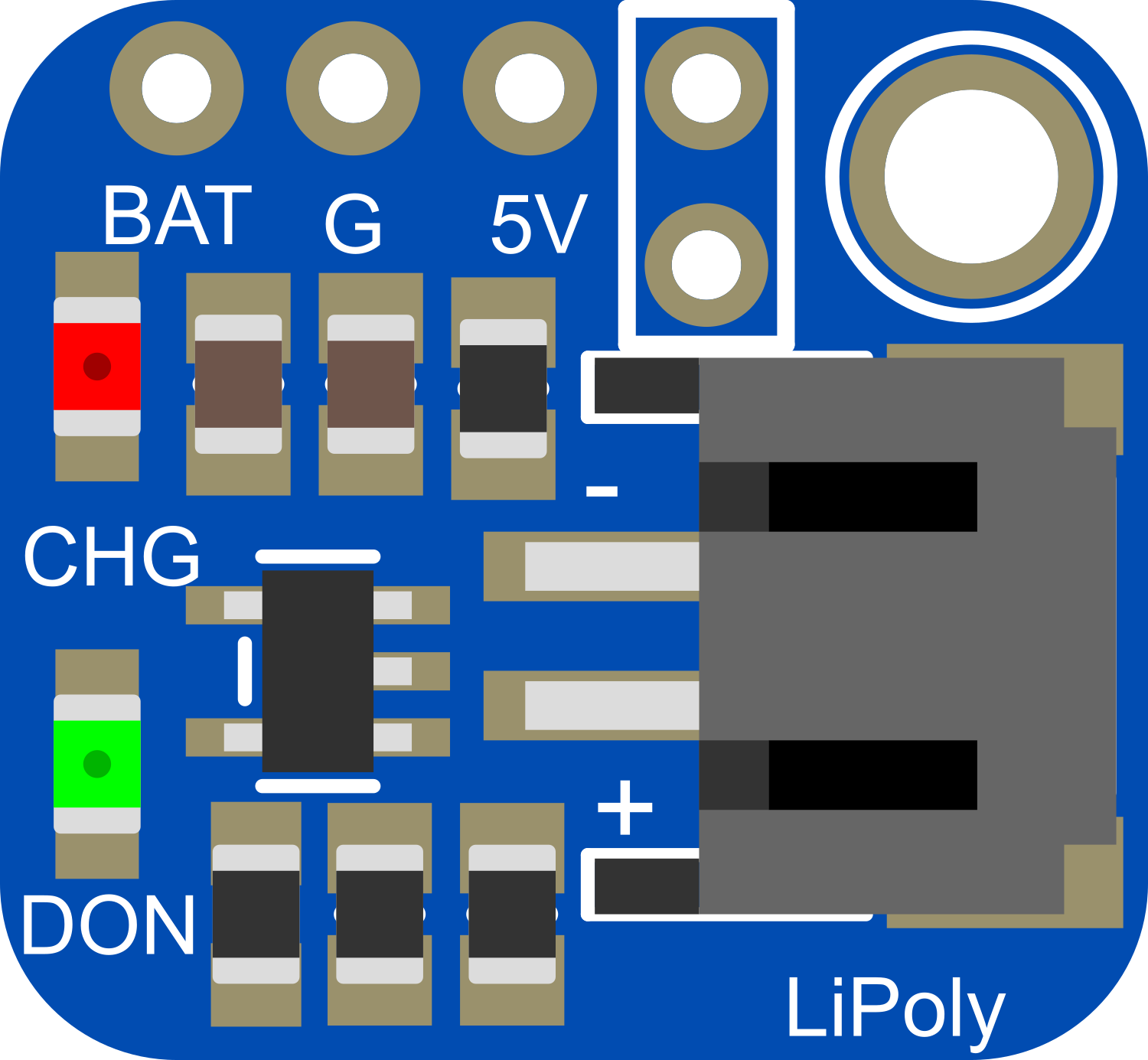
Pin Configuration and Descriptions

Pin Description
BAT Battery connection point for LiPo battery (+)
GND Ground connection point
5V Regulated output, can be used to power external devices
USB Micro USB port for charging the LiPo battery
EN Enable pin for the regulator (active high)
GND Ground connection for the enable pin

Usage Instructions

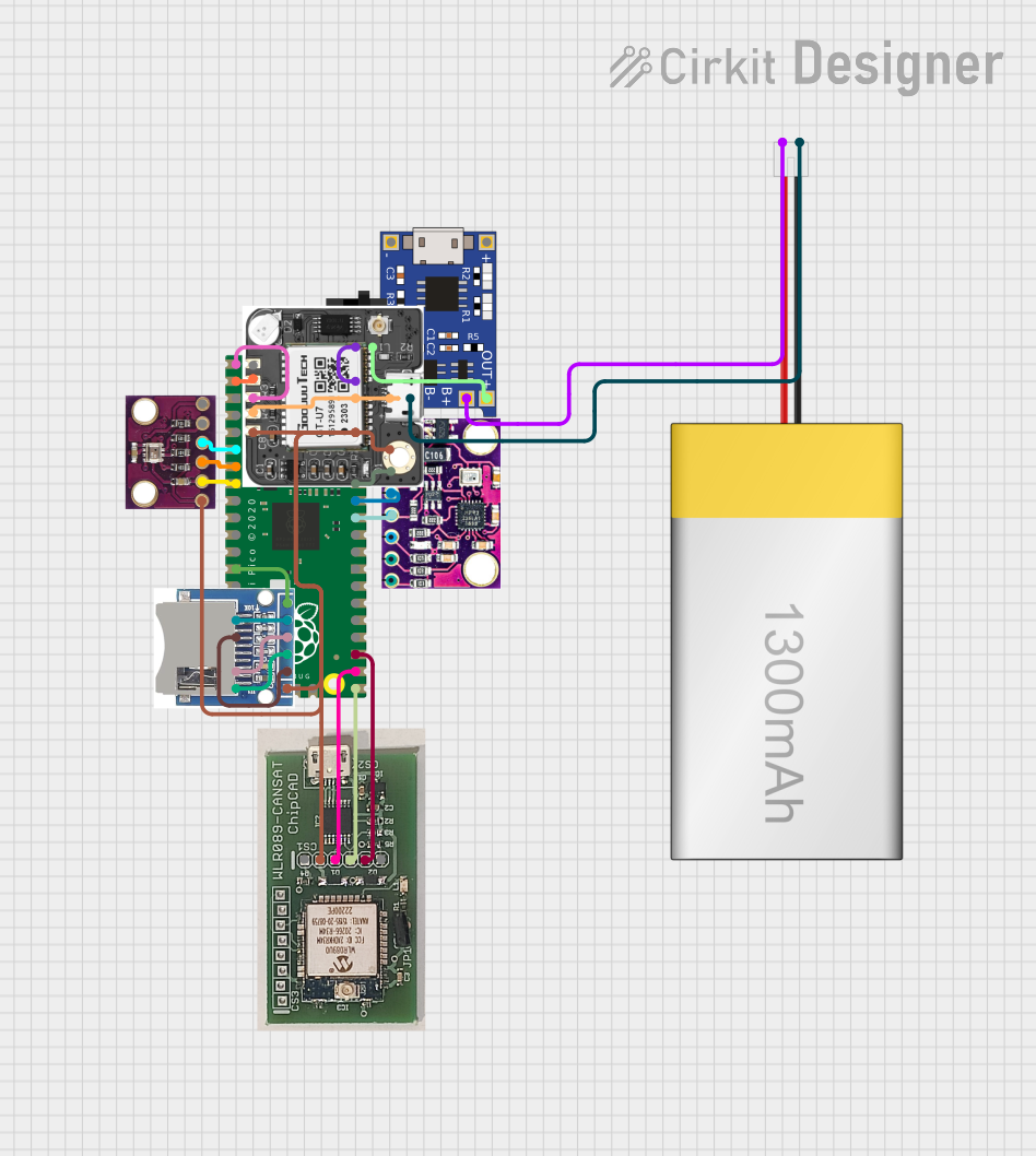
Integrating the LiPoly Backpack into a Circuit

  1. Connecting the Battery:

    • Connect the positive terminal of the LiPo battery to the BAT pin.
    • Connect the negative terminal of the LiPo battery to the GND pin.
  2. Powering Your Project:

    • Use the 5V pin to power your project. This pin provides a regulated output from the boost converter.
  3. Charging the Battery:

    • Connect a micro USB cable to the USB port and a 5V USB power source to charge the battery.
  4. Enabling/Disabling the Regulator:

    • The regulator can be enabled or disabled using the EN pin. Connect it to a high logic level to enable or leave it floating/disconnected to disable.

Important Considerations and Best Practices

  • Battery Safety: Always use LiPo batteries with a protection circuit and never leave them charging unattended.
  • Charging Current: The default charging current is 100mA. To adjust the current, you may need to replace the onboard resistor with the appropriate value.
  • Output Load: Ensure that the load connected to the 5V pin does not exceed the maximum output current rating.
  • Heat Dissipation: Be mindful of heat generation when charging or when powering high-current loads.

Troubleshooting and FAQs

Common Issues

  • Battery Not Charging:

    • Ensure the micro USB cable is properly connected and the power source is on.
    • Check the battery connections to the BAT and GND pins.
    • Verify that the battery is not already fully charged.
  • No Output Voltage:

    • Check if the EN pin is set to a high logic level.
    • Ensure that the battery is properly charged and connected.
    • Inspect the 5V pin and the connected load for any shorts or open circuits.

Solutions and Tips

  • If the battery is not charging, try a different USB cable or power source.
  • If the output voltage is not present, ensure that the EN pin is not accidentally grounded.
  • For any persistent issues, refer to the Adafruit support forums or contact technical support.

Example Code for Arduino UNO

// Example code to read the battery voltage using an Arduino UNO

const int batteryPin = A0; // Analog pin connected to voltage divider output

void setup() {
  Serial.begin(9600);
}

void loop() {
  int sensorValue = analogRead(batteryPin); // Read the analog value
  float voltage = sensorValue * (5.0 / 1023.0); // Convert to voltage
  Serial.print("Battery Voltage: ");
  Serial.println(voltage);
  delay(1000); // Wait for a second before reading again
}

Note: This code assumes you have a voltage divider connected to the BAT pin to bring the battery voltage within the range of the Arduino analog input. Adjust the voltage divider values accordingly.

Remember to keep code comments concise and within the 80 character line length limit.