How to Use step down buck converter lm2596: Examples, Pinouts, and Specs
Introduction
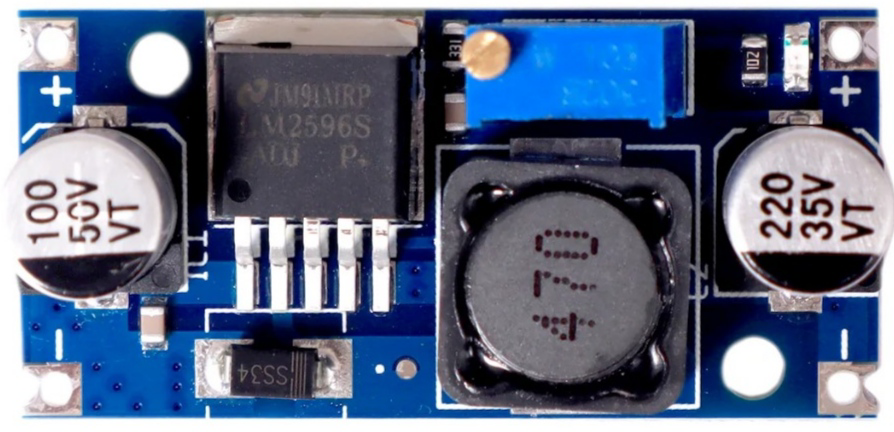
The LM2596, manufactured by STMicroelectronics (Part ID: UNO), is a step-down (buck) voltage regulator designed for efficient voltage conversion. It is capable of converting a higher input voltage to a stable, lower output voltage with high efficiency. The LM2596 can deliver up to 3A of output current, making it suitable for a wide range of power supply applications. It also includes built-in thermal shutdown and current limiting features to ensure safe operation.
Explore Projects Built with step down buck converter lm2596


Explore Projects Built with step down buck converter lm2596
Common Applications and Use Cases
- DC-DC power supply modules
- Battery-powered devices
- Voltage regulation for microcontrollers and sensors
- LED drivers
- Industrial and automotive electronics
Technical Specifications
Key Technical Details
| Parameter | Value |
|---|---|
| Input Voltage Range | 4.5V to 40V |
| Output Voltage Range | 1.23V to 37V (adjustable) |
| Output Current | Up to 3A |
| Efficiency | Up to 90% |
| Switching Frequency | 150 kHz |
| Thermal Shutdown | Yes |
| Current Limiting | Yes |
| Package Type | TO-220, TO-263, or similar |
Pin Configuration and Descriptions
| Pin Number | Pin Name | Description |
|---|---|---|
| 1 | VIN | Input voltage pin (4.5V to 40V) |
| 2 | VOUT | Regulated output voltage pin |
| 3 | GND | Ground pin |
| 4 | FB (Feedback) | Feedback pin for setting the output voltage |
| 5 | ON/OFF | Enable/disable pin (optional, depending on model) |
Usage Instructions
How to Use the LM2596 in a Circuit
- Input Voltage: Connect the input voltage (4.5V to 40V) to the VIN pin. Ensure the input voltage is at least 3V higher than the desired output voltage for proper regulation.
- Output Voltage Adjustment: Use a voltage divider circuit connected to the FB pin to set the desired output voltage. The formula for the output voltage is: [ V_{OUT} = V_{REF} \times \left(1 + \frac{R1}{R2}\right) ] where ( V_{REF} ) is 1.23V, and ( R1 ) and ( R2 ) are the resistors in the voltage divider.
- Output Capacitor: Place a low-ESR capacitor (e.g., 100µF) at the output to stabilize the voltage.
- Input Capacitor: Add a capacitor (e.g., 100µF) at the input to filter noise and improve stability.
- Inductor Selection: Choose an inductor with a suitable current rating (greater than 3A) and appropriate inductance value (e.g., 33µH) for your application.
- Enable Pin: If the ON/OFF pin is available, connect it to GND to enable the regulator or to VIN to disable it.
Important Considerations and Best Practices
- Ensure proper heat dissipation by using a heatsink or adequate PCB layout for thermal management.
- Use low-ESR capacitors to minimize output voltage ripple.
- Avoid exceeding the maximum input voltage (40V) or output current (3A) to prevent damage.
- Place all components (capacitors, inductor, etc.) as close as possible to the LM2596 to reduce noise and improve performance.
Example: Connecting LM2596 to an Arduino UNO
The LM2596 can be used to power an Arduino UNO by stepping down a higher voltage (e.g., 12V) to 5V. Below is an example circuit and Arduino code:
Circuit Connections
- Connect the input voltage (e.g., 12V) to the VIN pin of the LM2596.
- Set the output voltage to 5V using the feedback resistors.
- Connect the VOUT pin of the LM2596 to the 5V pin of the Arduino UNO.
- Connect the GND pin of the LM2596 to the GND pin of the Arduino UNO.
Arduino Code Example
// Example code to blink an LED using Arduino UNO powered by LM2596
// Ensure the LM2596 output is set to 5V before connecting to the Arduino

const int ledPin = 13; // Pin connected to the onboard LED

void setup() {
  pinMode(ledPin, OUTPUT); // Set the LED pin as an output
}

void loop() {
  digitalWrite(ledPin, HIGH); // Turn the LED on
  delay(1000);                // Wait for 1 second
  digitalWrite(ledPin, LOW);  // Turn the LED off
  delay(1000);                // Wait for 1 second
}
Troubleshooting and FAQs
Common Issues and Solutions
Output Voltage is Incorrect
- Cause: Incorrect feedback resistor values or poor connections.
- Solution: Double-check the resistor values and connections. Use a multimeter to verify the output voltage.
Excessive Heat
- Cause: High input voltage, high output current, or insufficient cooling.
- Solution: Use a heatsink or improve PCB thermal design. Reduce the input voltage if possible.
No Output Voltage
- Cause: Faulty connections, damaged component, or disabled ON/OFF pin.
- Solution: Verify all connections. Ensure the ON/OFF pin is connected to GND to enable the regulator.
High Output Ripple
- Cause: Poor capacitor selection or placement.
- Solution: Use low-ESR capacitors and place them close to the LM2596.
FAQs
Can the LM2596 be used with a 3.3V output?
- Yes, the LM2596 can be configured for a 3.3V output by adjusting the feedback resistors.
What is the maximum input voltage for the LM2596?
- The maximum input voltage is 40V. Exceeding this value may damage the component.
Can the LM2596 power a Raspberry Pi?
- Yes, the LM2596 can power a Raspberry Pi if configured to output 5V and the current demand does not exceed 3A.
Is the LM2596 suitable for battery-powered applications?
- Yes, the LM2596 is highly efficient and suitable for battery-powered devices, provided the input voltage is within the specified range.
By following this documentation, users can effectively integrate the LM2596 into their projects and troubleshoot common issues.