Cirkit Designer Logo
Cirkit Designer
Your all-in-one circuit design IDE
Home / 
Component Documentation

How to Use Adafruit FT232H Breakout - USB C and STEMMA QT: Examples, Pinouts, and Specs

Image of Adafruit FT232H Breakout - USB C and STEMMA QT
Cirkit Designer LogoDesign with Adafruit FT232H Breakout - USB C and STEMMA QT in Cirkit Designer

Introduction

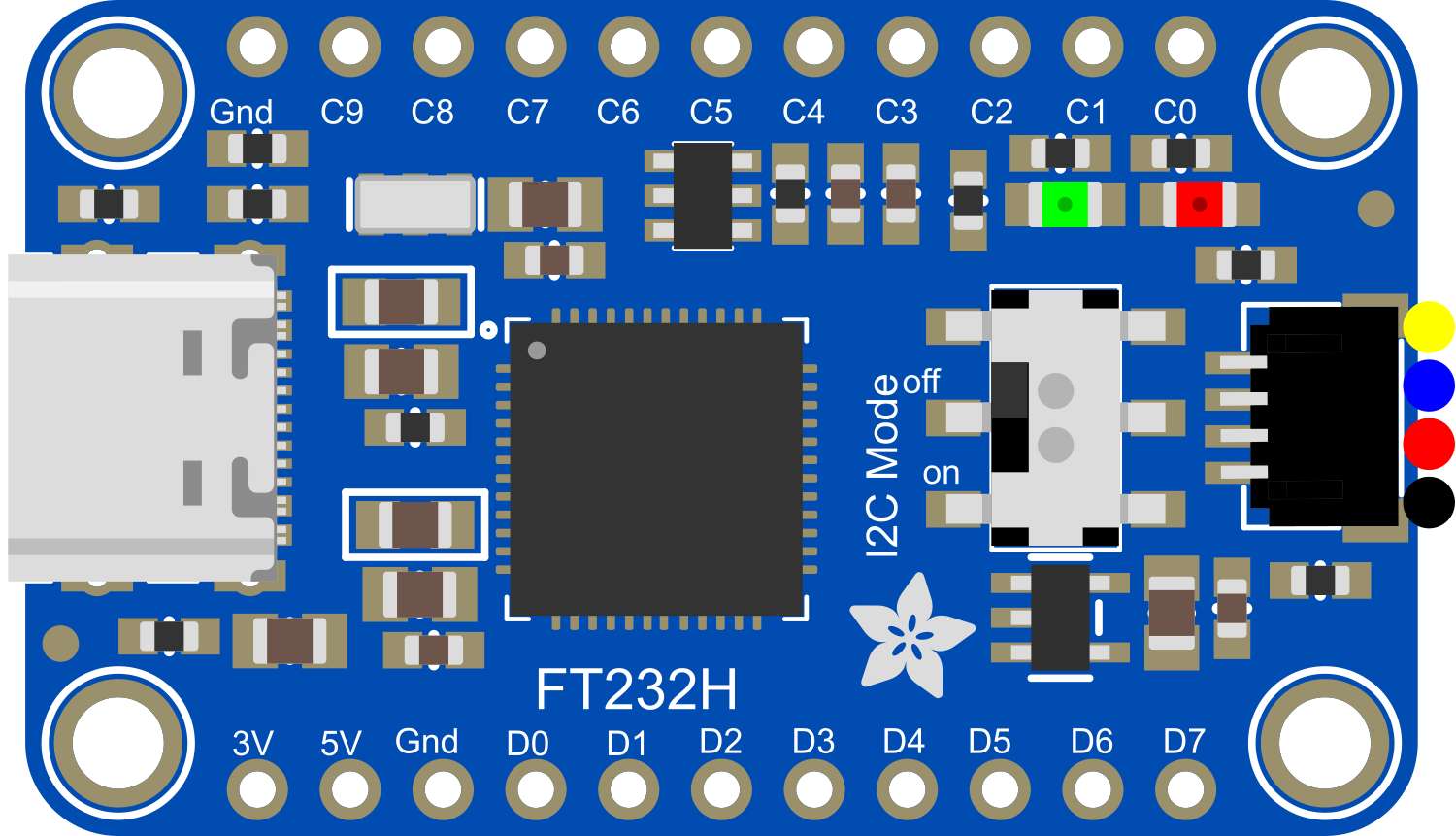
The Adafruit FT232H Breakout is a multifunctional USB to serial converter module that bridges USB connections to a variety of communication protocols such as GPIO, SPI, and I2C. This breakout board is designed to simplify interfacing with different electronic components and modules by leveraging the capabilities of the FT232H chip. It features a USB C connector for modern connectivity and a STEMMA QT connector for quick and easy I2C interfacing. This board is commonly used in applications that require communication between a computer and peripheral hardware, such as for sensor data acquisition, controlling actuators, or interfacing with microcontrollers and other integrated circuits.

Explore Projects Built with Adafruit FT232H Breakout - USB C and STEMMA QT

Use Cirkit Designer to design, explore, and prototype these projects online. Some projects support real-time simulation. Click "Open Project" to start designing instantly!
ESP32-Powered NTP Clock with Multiple GC9A01 Displays
Image of InfoOrbsFork: A project utilizing Adafruit FT232H Breakout - USB C and STEMMA QT in a practical application
This circuit features an ESP32 microcontroller connected to multiple GC9A01 displays and a USB Type C breakout for power. The ESP32 runs a sketch to retrieve the current time from an NTP server over WiFi and displays the hours and minutes across the GC9A01 displays, with each display showing a single digit or colon separator. Pushbuttons are connected to GPIOs on the ESP32, potentially for user input to control display functions or settings.
Cirkit Designer LogoOpen Project in Cirkit Designer
ESP32 CAM Wi-Fi Enabled Camera Module with USB Power
Image of abc: A project utilizing Adafruit FT232H Breakout - USB C and STEMMA QT in a practical application
This circuit consists of an ESP32 CAM module powered by a Micro USB breakout board. The USB breakout board supplies 5V and ground to the ESP32 CAM, enabling it to function and perform tasks such as image capture and processing.
Cirkit Designer LogoOpen Project in Cirkit Designer
ESP32-CAM and IR Sensor Interface with USB UART Communication
Image of esp32cam parking: A project utilizing Adafruit FT232H Breakout - USB C and STEMMA QT in a practical application
This circuit features an ESP32 CAM module interfaced with an IR sensor and a SparkFun USB UART Breakout board. The ESP32 CAM provides power to the IR sensor and receives its output signal, likely for processing or triggering camera actions based on IR detection. The USB UART Breakout board is connected to the ESP32 CAM for serial communication, enabling programming, debugging, or data exchange with a computer.
Cirkit Designer LogoOpen Project in Cirkit Designer
FTDI to UART Adapter with J26 Connector
Image of J26 CLOSEUP: A project utilizing Adafruit FT232H Breakout - USB C and STEMMA QT in a practical application
This circuit connects an FTDI USB-to-serial converter to a standard serial interface via a J26 connector. It facilitates serial communication by linking the ground, transmit, receive, data terminal ready, and request to send signals between the FTDI chip and the J26 connector.
Cirkit Designer LogoOpen Project in Cirkit Designer

Explore Projects Built with Adafruit FT232H Breakout - USB C and STEMMA QT

Use Cirkit Designer to design, explore, and prototype these projects online. Some projects support real-time simulation. Click "Open Project" to start designing instantly!
Image of InfoOrbsFork: A project utilizing Adafruit FT232H Breakout - USB C and STEMMA QT in a practical application
ESP32-Powered NTP Clock with Multiple GC9A01 Displays
This circuit features an ESP32 microcontroller connected to multiple GC9A01 displays and a USB Type C breakout for power. The ESP32 runs a sketch to retrieve the current time from an NTP server over WiFi and displays the hours and minutes across the GC9A01 displays, with each display showing a single digit or colon separator. Pushbuttons are connected to GPIOs on the ESP32, potentially for user input to control display functions or settings.
Cirkit Designer LogoOpen Project in Cirkit Designer
Image of abc: A project utilizing Adafruit FT232H Breakout - USB C and STEMMA QT in a practical application
ESP32 CAM Wi-Fi Enabled Camera Module with USB Power
This circuit consists of an ESP32 CAM module powered by a Micro USB breakout board. The USB breakout board supplies 5V and ground to the ESP32 CAM, enabling it to function and perform tasks such as image capture and processing.
Cirkit Designer LogoOpen Project in Cirkit Designer
Image of esp32cam parking: A project utilizing Adafruit FT232H Breakout - USB C and STEMMA QT in a practical application
ESP32-CAM and IR Sensor Interface with USB UART Communication
This circuit features an ESP32 CAM module interfaced with an IR sensor and a SparkFun USB UART Breakout board. The ESP32 CAM provides power to the IR sensor and receives its output signal, likely for processing or triggering camera actions based on IR detection. The USB UART Breakout board is connected to the ESP32 CAM for serial communication, enabling programming, debugging, or data exchange with a computer.
Cirkit Designer LogoOpen Project in Cirkit Designer
Image of J26 CLOSEUP: A project utilizing Adafruit FT232H Breakout - USB C and STEMMA QT in a practical application
FTDI to UART Adapter with J26 Connector
This circuit connects an FTDI USB-to-serial converter to a standard serial interface via a J26 connector. It facilitates serial communication by linking the ground, transmit, receive, data terminal ready, and request to send signals between the FTDI chip and the J26 connector.
Cirkit Designer LogoOpen Project in Cirkit Designer

Technical Specifications

Key Technical Details

  • Chipset: FT232H High-Speed USB 2.0 to Serial/Parallel Interface
  • USB Connector: USB Type-C
  • Logic Voltage Levels: 3.3V (5V tolerant)
  • Max Current Output: 500mA (combined for VCC and GND pins)
  • GPIO Pins: 8, configurable as digital I/O
  • Serial Protocols Supported: UART, I2C, SPI, JTAG, and more
  • Operating Temperature Range: -40°C to +85°C

Pin Configuration and Descriptions

Pin Number Name Description
1 GND Ground connection
2 C0 Configurable GPIO/Chip Select for SPI
3 C1 Configurable GPIO/MISO for SPI
4 C2 Configurable GPIO/MOSI for SPI
5 C3 Configurable GPIO/SCLK for SPI
6 C4 Configurable GPIO/SDA for I2C
7 C5 Configurable GPIO/SCL for I2C
8 C6 Configurable GPIO/Additional GPIO
9 C7 Configurable GPIO/Additional GPIO
10 VCC Power supply (3.3V output from USB)

Usage Instructions

Interfacing with a Circuit

  1. Powering the Board:

    • Connect the USB C cable to the FT232H breakout and your computer.
    • Ensure the drivers are installed on your computer for the FT232H to be recognized.
  2. Using GPIO Pins:

    • Configure the desired pins as input or output using the provided Adafruit libraries or FTDI drivers.
    • Connect the pins to the peripherals as required, ensuring that the voltage levels are compatible.
  3. Using SPI/I2C:

    • For SPI communication, connect C0 to CS, C1 to MISO, C2 to MOSI, and C3 to SCLK of your SPI device.
    • For I2C communication, connect C4 to SDA and C5 to SCL of your I2C device.
    • Use the Adafruit libraries to initiate and handle the communication protocols.

Important Considerations and Best Practices

  • Always ensure that the power supply is adequate and stable.
  • Be cautious of the logic voltage levels; the FT232H is 5V tolerant, but operates at 3.3V logic.
  • When using SPI or I2C, ensure that the devices are compatible with the FT232H's voltage levels.
  • Use proper decoupling capacitors close to the power pins of the devices connected to the FT232H.
  • Avoid static discharge by grounding yourself before handling the breakout board.

Troubleshooting and FAQs

Common Issues

  • Device Not Recognized: Ensure that the correct drivers are installed and that the USB cable is properly connected.
  • Communication Errors: Double-check wiring, ensure correct protocol configuration, and verify that the connected devices are powered and functioning.
  • Voltage Mismatch: If devices are not operating as expected, verify that the voltage levels are compatible between the FT232H and the connected peripherals.

Solutions and Tips

  • Driver Installation: Visit the Adafruit website for the latest drivers and installation guides for different operating systems.
  • Library Usage: Utilize the Adafruit FT232H library for Python to simplify the use of GPIO, SPI, and I2C.
  • Voltage Level Shifting: If necessary, use a level shifter to match the voltage levels between the FT232H and other devices in the circuit.

Example Code for Arduino UNO

The following is an example of how to use the FT232H to blink an LED connected to pin C0 configured as a GPIO output. This example assumes you have the Adafruit FT232H library installed.

#include <Adafruit_GPIO.h>
#include <Adafruit_FT232H.h>

// Create an FT232H object
Adafruit_FT232H ft232h;

void setup() {
  // Initialize the FT232H
  ft232h.begin();

  // Configure pin C0 as an output
  ft232h.pinMode(0, OUTPUT);
}

void loop() {
  // Turn the LED on
  ft232h.digitalWrite(0, HIGH);
  delay(500);

  // Turn the LED off
  ft232h.digitalWrite(0, LOW);
  delay(500);
}

Remember to adjust the pin numbers and logic according to your specific setup and requirements.