How to Use 10 Port POE+ DIN Switch SFP+ 1gbe: Examples, Pinouts, and Specs
Introduction
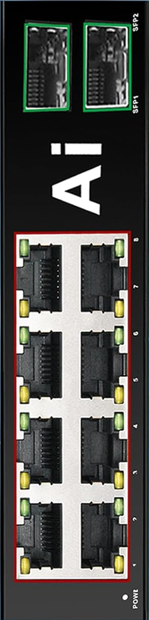
The 10 Port POE+ DIN Switch SFP+ 1gbe by ienRon is a robust, industrial-grade Power over Ethernet (PoE) switch designed for DIN rail mounting. It features 10 ports, including support for PoE+ (802.3at) to power connected devices and SFP+ for high-speed 1 Gbps fiber or copper connections. This switch is ideal for industrial environments requiring reliable network connectivity and power delivery, such as factory automation, surveillance systems, and IoT deployments.
Explore Projects Built with 10 Port POE+ DIN Switch SFP+ 1gbe


Explore Projects Built with 10 Port POE+ DIN Switch SFP+ 1gbe
Common Applications and Use Cases
- Industrial Automation: Connect and power PLCs, sensors, and other industrial devices.
- Surveillance Systems: Power IP cameras and transmit video data over a high-speed network.
- IoT Deployments: Provide connectivity and power to IoT devices in smart factories or buildings.
- Edge Computing: Enable high-speed data transfer for edge devices in remote or harsh environments.
Technical Specifications
The following table outlines the key technical details of the 10 Port POE+ DIN Switch SFP+ 1gbe:
| Specification | Details |
|---|---|
| Manufacturer | ienRon |
| Model | 10 Port POE+ DIN Switch SFP+ 1gbe |
| Number of Ports | 10 (8 PoE+ ports, 2 SFP+ ports) |
| PoE Standard | IEEE 802.3at (PoE+) |
| PoE Power Budget | 240W (shared across all PoE ports) |
| Data Rate | 1 Gbps (Gigabit Ethernet) |
| SFP+ Support | 1 Gbps fiber or copper modules |
| Input Voltage | 48-57V DC |
| Operating Temperature | -40°C to 75°C |
| Mounting | DIN rail |
| Dimensions | 150mm x 120mm x 50mm |
| Certifications | CE, FCC, RoHS |
Pin Configuration and Descriptions
The switch does not have traditional pins but includes ports and connectors. Below is a description of the ports:
| Port/Connector | Description |
|---|---|
| PoE+ Ports (1-8) | Gigabit Ethernet ports with PoE+ support for powering devices (up to 30W/port). |
| SFP+ Ports (9-10) | High-speed ports for fiber or copper SFP+ modules. |
| Power Input | Terminal block for 48-57V DC input. |
| Grounding Point | Grounding screw for electrical safety. |
Usage Instructions
How to Use the Component in a Network
- Mounting: Secure the switch to a DIN rail in your industrial environment.
- Power Connection: Connect a 48-57V DC power supply to the terminal block. Ensure proper grounding.
- Device Connection:
- Use Ethernet cables to connect PoE-compatible devices (e.g., IP cameras, access points) to ports 1-8.
- Insert SFP+ modules into ports 9-10 for high-speed uplink connections.
- Configuration: If the switch supports management features, access the web interface or CLI for advanced settings.
Important Considerations and Best Practices
- Power Budget: Ensure the total power consumption of connected PoE devices does not exceed the 240W budget.
- Cable Quality: Use high-quality Cat5e or Cat6 cables for PoE ports to ensure reliable power and data transmission.
- SFP+ Modules: Use compatible SFP+ modules for fiber or copper connections. Check the manufacturer's compatibility list.
- Environment: Operate the switch within the specified temperature range (-40°C to 75°C) for optimal performance.
Example: Connecting to an Arduino UNO
While the switch itself does not directly interface with an Arduino UNO, it can be used to power and connect network-enabled Arduino projects. For example, if using an Ethernet shield with the Arduino, connect the shield to one of the PoE+ ports for both power and data.
#include <SPI.h>
#include <Ethernet.h>

// MAC address and IP address for the Arduino Ethernet Shield
byte mac[] = { 0xDE, 0xAD, 0xBE, 0xEF, 0xFE, 0xED };
IPAddress ip(192, 168, 1, 177);

void setup() {
  // Initialize Ethernet connection
  if (Ethernet.begin(mac) == 0) {
    // If DHCP fails, use a static IP address
    Ethernet.begin(mac, ip);
  }
  Serial.begin(9600);
  while (!Serial) {
    ; // Wait for serial port to connect
  }
  Serial.println("Ethernet connected");
}

void loop() {
  // Example: Send a message over the network
  Serial.println("Running network tasks...");
  delay(1000);
}
Troubleshooting and FAQs
Common Issues Users Might Face
No Power to Devices:
- Cause: Insufficient power supply or exceeded PoE power budget.
- Solution: Verify the power supply voltage (48-57V DC) and ensure the total power consumption of connected devices is within the 240W budget.
No Network Connectivity:
- Cause: Faulty cables or incorrect configuration.
- Solution: Check Ethernet cables for damage and ensure proper connections. If the switch is managed, verify the configuration settings.
Overheating:
- Cause: Operating in an environment outside the specified temperature range.
- Solution: Ensure the switch is installed in a well-ventilated area within the -40°C to 75°C range.
SFP+ Module Not Detected:
- Cause: Incompatible or improperly seated module.
- Solution: Use a compatible SFP+ module and ensure it is securely inserted.
Solutions and Tips for Troubleshooting
- LED Indicators: Use the LED indicators on the switch to diagnose issues (e.g., power, link, and activity status).
- Firmware Updates: Check the manufacturer's website for firmware updates to improve performance and fix bugs.
- Support: Contact ienRon technical support for assistance with advanced troubleshooting.
This documentation provides a comprehensive guide to using the 10 Port POE+ DIN Switch SFP+ 1gbe effectively in industrial applications.