
How to Use KONTAKTOR + OVERLOAD: Examples, Pinouts, and Specs
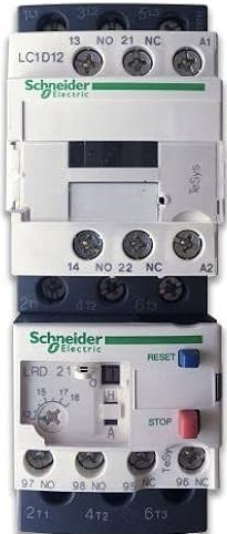
 Design with KONTAKTOR + OVERLOAD in Cirkit Designer
Introduction
The Schneider MCE 2-25 is a compact and reliable contactor with an integrated overload relay, designed for motor control and protection applications. This component combines the functionality of a contactor and an overload relay into a single unit, simplifying wiring and reducing panel space requirements. It is widely used in industrial automation, motor starters, and control panels to ensure safe and efficient operation of electric motors.
Explore Projects Built with KONTAKTOR + OVERLOAD
 Open Project in Cirkit Designer
 Open Project in Cirkit Designer
 Open Project in Cirkit Designer
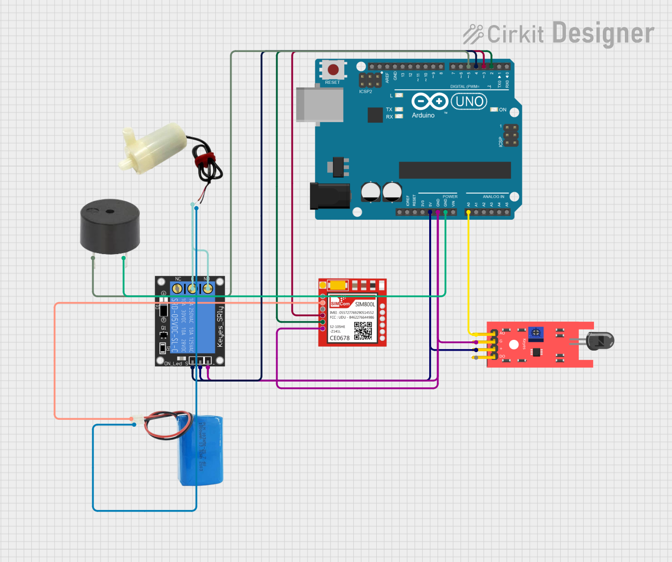 Open Project in Cirkit Designer
Explore Projects Built with KONTAKTOR + OVERLOAD
Open Project in Cirkit DesignerOpen Project in Cirkit DesignerOpen Project in Cirkit DesignerOpen Project in Cirkit DesignerCommon Applications and Use Cases
- Motor control and protection in industrial machinery
- HVAC systems
- Conveyor systems
- Pump control panels
- Automation systems requiring compact motor starters
Technical Specifications
Key Technical Details
| Parameter | Value |
|---|---|
| Manufacturer | Schneider |
| Part ID | MCE 2-25 |
| Rated Operational Voltage | Up to 690V AC |
| Rated Current | 25A |
| Control Voltage | 24V AC/DC, 110V AC, or 230V AC |
| Frequency | 50/60 Hz |
| Overload Relay Range | 0.1A to 25A (adjustable) |
| Number of Poles | 3P (Three-phase) |
| Mechanical Durability | 10 million operations |
| Electrical Durability | 1 million operations |
| Mounting Type | DIN rail or panel mount |
| Operating Temperature | -20°C to +60°C |
Pin Configuration and Descriptions
Power Terminals
| Terminal Label | Description |
|---|---|
| L1, L2, L3 | Input terminals for three-phase power |
| T1, T2, T3 | Output terminals to the motor |
Control Terminals
| Terminal Label | Description |
|---|---|
| A1, A2 | Coil terminals for control voltage |
| 95, 96 | Normally closed (NC) overload relay |
| 97, 98 | Normally open (NO) overload relay |
Usage Instructions
How to Use the Component in a Circuit
Wiring the Power Circuit:
- Connect the three-phase power supply to the input terminals (L1, L2, L3).
- Connect the motor leads to the output terminals (T1, T2, T3).
Wiring the Control Circuit:
- Supply the appropriate control voltage to the coil terminals (A1, A2) based on the rated control voltage of the contactor.
- Use the overload relay terminals (95, 96, 97, 98) to integrate the overload protection into the control circuit.
Adjusting the Overload Relay:
- Set the overload relay to match the motor's full-load current using the adjustable dial on the relay.
Testing the Circuit:
- After wiring, test the circuit by energizing the control coil and verifying that the contactor operates correctly.
- Ensure the overload relay trips when the motor current exceeds the set value.
Important Considerations and Best Practices
- Always verify the voltage and current ratings of the contactor and overload relay before installation.
- Ensure proper tightening of all terminal connections to avoid overheating or loose connections.
- Use appropriate fuses or circuit breakers upstream for additional protection.
- Regularly inspect the contactor for signs of wear or damage, especially in high-duty-cycle applications.
- Avoid exceeding the rated operating temperature to ensure long-term reliability.
Example: Connecting to an Arduino UNO
The MCE 2-25 can be controlled using an Arduino UNO by energizing the contactor coil with a relay module. Below is an example code snippet for controlling the contactor using a digital output pin on the Arduino.
// Example: Controlling Schneider MCE 2-25 with Arduino UNO
// This code energizes the contactor coil using a relay module connected to pin 7.

const int relayPin = 7; // Define the pin connected to the relay module

void setup() {
  pinMode(relayPin, OUTPUT); // Set the relay pin as an output
  digitalWrite(relayPin, LOW); // Ensure the relay is off initially
}

void loop() {
  digitalWrite(relayPin, HIGH); // Turn on the relay (energize contactor coil)
  delay(5000); // Keep the contactor energized for 5 seconds
  digitalWrite(relayPin, LOW); // Turn off the relay (de-energize contactor coil)
  delay(5000); // Wait for 5 seconds before repeating
}
Note: Use a relay module with an appropriate voltage rating to interface between the Arduino and the contactor coil. Ensure the Arduino's power supply is isolated from the contactor's power circuit.
Troubleshooting and FAQs
Common Issues and Solutions
Contactor Does Not Energize:
- Cause: Incorrect control voltage or loose connections.
- Solution: Verify the control voltage matches the rated coil voltage and check all connections.
Overload Relay Trips Frequently:
- Cause: Overload relay set too low or motor drawing excessive current.
- Solution: Adjust the overload relay to match the motor's full-load current. Inspect the motor for faults.
Excessive Heat on Terminals:
- Cause: Loose or corroded connections.
- Solution: Tighten all terminal screws and clean any corrosion.
Humming Noise from Contactor:
- Cause: Coil voltage fluctuation or mechanical wear.
- Solution: Ensure stable control voltage and inspect the contactor for mechanical issues.
FAQs
Q: Can the MCE 2-25 be used for single-phase motors?
A: Yes, but only two poles of the contactor will be used. Ensure proper wiring and overload relay adjustment.Q: How do I reset the overload relay after a trip?
A: Press the reset button on the overload relay or power cycle the control circuit, depending on the model.Q: Can I use the MCE 2-25 in outdoor environments?
A: The MCE 2-25 is not rated for outdoor use unless installed in a weatherproof enclosure.Q: What is the lifespan of the contactor?
A: The MCE 2-25 has a mechanical durability of 10 million operations and an electrical durability of 1 million operations under normal conditions.