How to Use cyton: Examples, Pinouts, and Specs
It seems there is some confusion in the description provided. Based on the manufacturer (Cytron) and the part ID (MD30C), this component is likely the Cytron MD30C motor driver, which is an electronic module used to control DC motors. I will proceed to create documentation for the Cytron MD30C motor driver. If this is incorrect, please clarify.
Cytron MD30C Documentation
Introduction
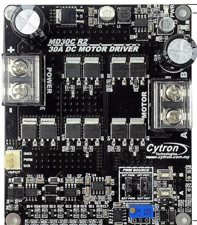
The Cytron MD30C is a high-performance motor driver designed to control brushed DC motors. It supports a wide range of input voltages and can handle high current loads, making it suitable for various robotics and industrial applications. The MD30C is equipped with multiple control modes, including PWM and analog, and features built-in protection mechanisms for safe and reliable operation.
Common Applications
- Robotics: Driving wheels or actuators in robotic systems
- Conveyor belts: Controlling motorized conveyor systems
- Automated systems: Industrial automation requiring precise motor control
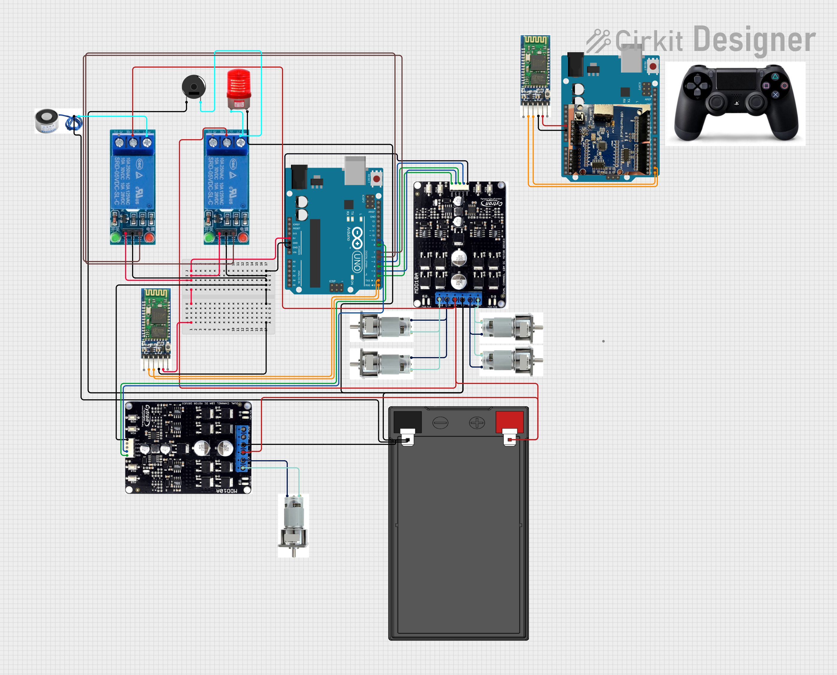
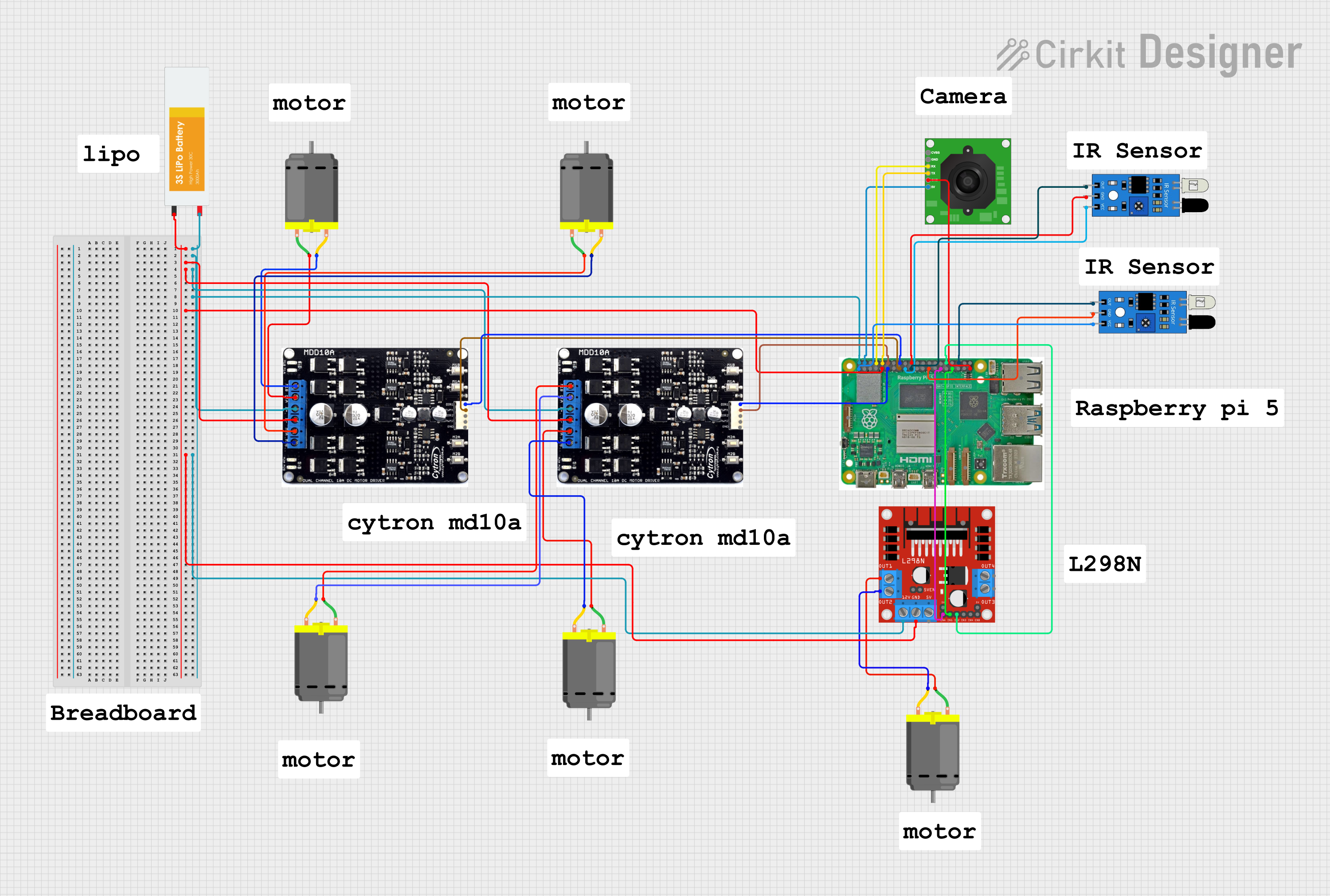
- Educational projects: Motor control in Arduino or Raspberry Pi-based projects
Technical Specifications
The following table outlines the key technical specifications of the Cytron MD30C motor driver:
| Parameter | Specification |
|---|---|
| Input Voltage Range | 7V to 30V DC |
| Continuous Current | 30A |
| Peak Current | 80A (for 10 seconds) |
| Control Modes | PWM, Analog, RC (Radio Control) |
| PWM Frequency | Up to 20 kHz |
| Logic Voltage | 3.3V or 5V compatible |
| Protection Features | Overcurrent, Overtemperature, Reverse Polarity |
| Dimensions | 84mm x 62mm x 28mm |
| Weight | 120g |
Pin Configuration and Descriptions
The Cytron MD30C has the following pin configuration:
| Pin Name | Description |
|---|---|
| VM | Motor power supply input (7V to 30V DC) |
| GND | Ground connection |
| M+ | Motor positive terminal |
| M- | Motor negative terminal |
| PWM | Pulse Width Modulation input for speed control |
| DIR | Direction control input (HIGH for forward, LOW for reverse) |
| AN | Analog input for speed control (alternative to PWM) |
| RC | Radio Control input for speed control (e.g., from an RC receiver) |
| EN | Enable pin (HIGH to enable the motor driver, LOW to disable) |
| FG | Frequency generator output for motor speed feedback (optional use) |
Usage Instructions
How to Use the Cytron MD30C in a Circuit
- Power Supply: Connect a DC power supply (7V to 30V) to the
VMandGNDpins. Ensure the power supply can provide sufficient current for your motor. - Motor Connection: Connect the motor terminals to the
M+andM-pins. - Control Input: Choose a control mode (PWM, Analog, or RC):
- For PWM control, connect a PWM signal to the
PWMpin and set theDIRpin for direction. - For analog control, provide a voltage (0V to 5V) to the
ANpin. - For RC control, connect an RC signal to the
RCpin.
- For PWM control, connect a PWM signal to the
- Enable the Driver: Set the
ENpin HIGH to enable the motor driver. - Optional Feedback: Use the
FGpin to monitor motor speed if needed.
Important Considerations and Best Practices
- Heat Dissipation: The MD30C can handle high currents, but it may generate heat. Use a heatsink or active cooling if operating near the maximum current rating.
- Power Supply: Ensure the power supply voltage matches the motor's requirements and does not exceed 30V.
- Control Signal Compatibility: Verify that the control signals (PWM, Analog, or RC) are within the specified voltage range (3.3V or 5V).
- Protection Features: The MD30C includes built-in protection, but avoid prolonged operation at peak current to prevent damage.
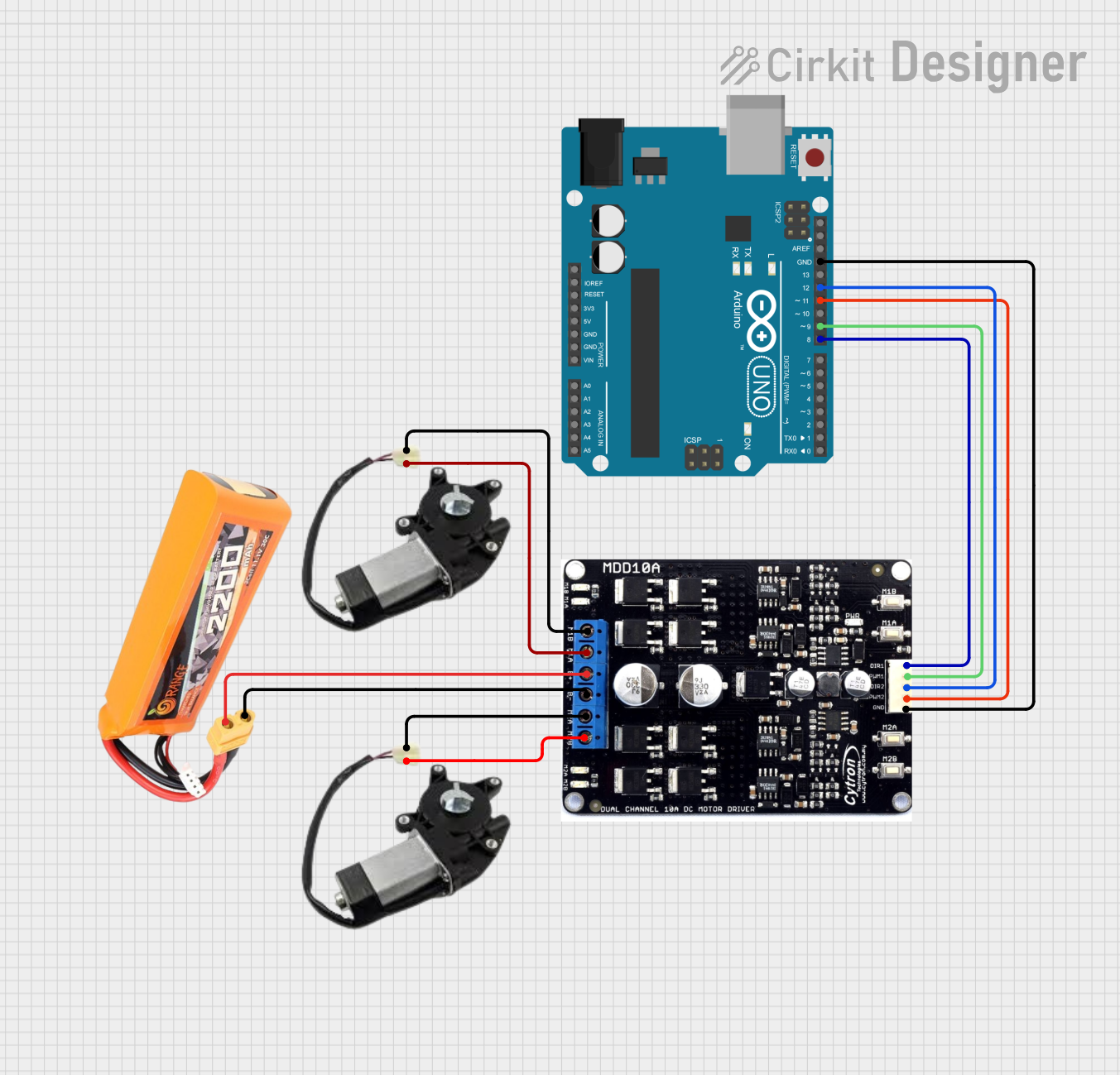
Example: Using the MD30C with an Arduino UNO
Below is an example of controlling a motor using the MD30C and an Arduino UNO with PWM:
// Define pin connections
const int pwmPin = 9;  // PWM signal connected to MD30C PWM pin
const int dirPin = 8;  // Direction control connected to MD30C DIR pin
const int enPin = 7;   // Enable pin connected to MD30C EN pin

void setup() {
  // Set pin modes
  pinMode(pwmPin, OUTPUT);
  pinMode(dirPin, OUTPUT);
  pinMode(enPin, OUTPUT);

  // Enable the motor driver
  digitalWrite(enPin, HIGH);
}

void loop() {
  // Set motor direction to forward
  digitalWrite(dirPin, HIGH);

  // Gradually increase motor speed
  for (int speed = 0; speed <= 255; speed++) {
    analogWrite(pwmPin, speed);  // Send PWM signal to control speed
    delay(20);                   // Wait for 20ms
  }

  // Gradually decrease motor speed
  for (int speed = 255; speed >= 0; speed--) {
    analogWrite(pwmPin, speed);
    delay(20);
  }

  // Set motor direction to reverse
  digitalWrite(dirPin, LOW);

  // Repeat the speed ramp-up and ramp-down
  for (int speed = 0; speed <= 255; speed++) {
    analogWrite(pwmPin, speed);
    delay(20);
  }
  for (int speed = 255; speed >= 0; speed--) {
    analogWrite(pwmPin, speed);
    delay(20);
  }
}
Troubleshooting and FAQs
Common Issues
Motor Not Running
- Ensure the
ENpin is set HIGH to enable the motor driver. - Verify the power supply voltage and current are sufficient for the motor.
- Check the control signal connections (PWM, Analog, or RC).
- Ensure the
Overheating
- Ensure proper heat dissipation using a heatsink or fan.
- Avoid operating at peak current for extended periods.
Motor Running in the Wrong Direction
- Check the
DIRpin state. Set it HIGH for forward and LOW for reverse. - Verify the motor connections to
M+andM-.
- Check the
No Response to Control Signals
- Confirm the control signal voltage levels are within the specified range (3.3V or 5V).
- Check for loose or incorrect wiring.
FAQs
Q: Can I use the MD30C with a 3.3V microcontroller?
A: Yes, the MD30C is compatible with both 3.3V and 5V logic levels.
Q: What happens if I reverse the power supply polarity?
A: The MD30C has built-in reverse polarity protection to prevent damage.
Q: Can I control two motors with one MD30C?
A: No, the MD30C is designed to control a single brushed DC motor.
Q: What is the purpose of the FG pin?
A: The FG pin provides a frequency signal proportional to the motor speed, which can be used for feedback in closed-loop control systems.
Explore Projects Built with cyton

Explore Projects Built with cyton