
How to Use RJ11 Jack: Examples, Pinouts, and Specs
 Design with RJ11 Jack in Cirkit Designer
Introduction
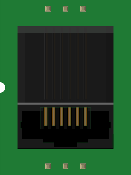
The RJ11 Jack is a widely used connector designed for telephone line connections. It features 6 positions and typically 2 or 4 contacts, making it ideal for transmitting analog voice signals or low-speed data. Its compact design and standardized pinout make it a staple in telecommunication systems and other low-voltage applications.
Explore Projects Built with RJ11 Jack
 Open Project in Cirkit Designer
 Open Project in Cirkit Designer
 Open Project in Cirkit Designer
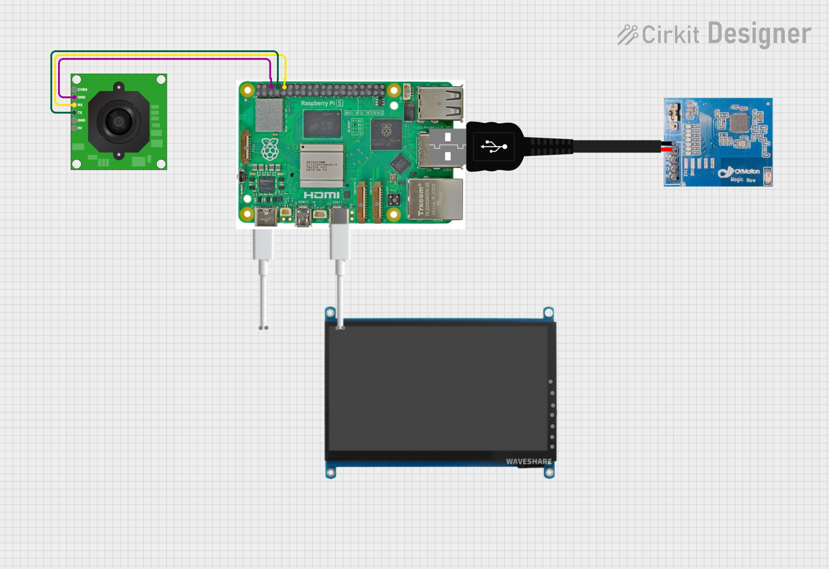 Open Project in Cirkit Designer
Explore Projects Built with RJ11 Jack
Open Project in Cirkit DesignerOpen Project in Cirkit DesignerOpen Project in Cirkit DesignerOpen Project in Cirkit DesignerCommon Applications and Use Cases
- Telephone line connections in residential and commercial setups
- DSL (Digital Subscriber Line) internet connections
- Interfacing with modems, fax machines, and telephony equipment
- Low-speed serial communication in embedded systems
Technical Specifications
Key Technical Details
- Connector Type: RJ11 (Registered Jack 11)
- Positions: 6 (6P)
- Contacts: 2 (6P2C) or 4 (6P4C)
- Voltage Rating: Up to 150V
- Current Rating: Typically 1.5A
- Contact Resistance: ≤ 20 mΩ
- Insulation Resistance: ≥ 500 MΩ
- Operating Temperature: -40°C to +85°C
- Durability: Rated for 500+ mating cycles
Pin Configuration and Descriptions
The RJ11 Jack pinout depends on the number of contacts (2 or 4). Below is the standard pin configuration for a 6P4C RJ11 Jack:
| Pin Number | Signal Name | Description |
|---|---|---|
| 1 | Not Connected | Unused in most configurations |
| 2 | Ring (-) | Negative side of the telephone line |
| 3 | Tip (+) | Positive side of the telephone line |
| 4 | Not Connected | Unused in most configurations |
| 5 | Not Connected | Unused in most configurations |
| 6 | Not Connected | Unused in most configurations |
For a 6P2C RJ11 Jack, only pins 2 and 3 are used (Ring and Tip).
Usage Instructions
How to Use the RJ11 Jack in a Circuit
Wiring the RJ11 Jack:
- Identify the Ring (-) and Tip (+) pins (pins 2 and 3 for 6P2C or 6P4C configurations).
- Connect the Ring pin to the negative side of the telephone line and the Tip pin to the positive side.
- For DSL or modem connections, ensure the correct polarity and wiring to avoid signal issues.
Mounting the RJ11 Jack:
- Use a PCB-mounted RJ11 Jack for circuit boards or a panel-mounted version for enclosures.
- Solder the pins securely to the PCB or use crimp connectors for cable terminations.
Interfacing with Microcontrollers:
- Use an optocoupler or isolation circuit to protect the microcontroller from high voltages on the telephone line.
- For data communication, connect the Ring and Tip pins to the appropriate UART or serial interface pins.
Important Considerations and Best Practices
- Polarity: Ensure correct polarity when connecting the RJ11 Jack to avoid damaging connected devices.
- Isolation: Use isolation circuits to protect sensitive electronics from voltage spikes on the telephone line.
- Cable Type: Use twisted-pair cables for better signal integrity and reduced interference.
- Compliance: Ensure compliance with local telecommunication standards when using the RJ11 Jack in telephone systems.
Example: Connecting an RJ11 Jack to an Arduino UNO
Below is an example of interfacing an RJ11 Jack with an Arduino UNO for detecting a telephone line signal:
// Example: Detecting a telephone line signal using an RJ11 Jack and Arduino UNO
// Note: Use an optocoupler or isolation circuit to protect the Arduino from high voltages.

const int ringPin = 2; // Pin connected to the Ring (-) line via an isolation circuit
const int tipPin = 3;  // Pin connected to the Tip (+) line via an isolation circuit

void setup() {
  pinMode(ringPin, INPUT); // Set Ring pin as input
  pinMode(tipPin, INPUT);  // Set Tip pin as input
  Serial.begin(9600);      // Initialize serial communication
}

void loop() {
  int ringState = digitalRead(ringPin); // Read the Ring line state
  int tipState = digitalRead(tipPin);  // Read the Tip line state

  // Check if there is a signal on the telephone line
  if (ringState == HIGH || tipState == HIGH) {
    Serial.println("Signal detected on the telephone line!");
  } else {
    Serial.println("No signal detected.");
  }

  delay(1000); // Wait for 1 second before checking again
}
Troubleshooting and FAQs
Common Issues and Solutions
No Signal Detected:
- Cause: Incorrect wiring or loose connections.
- Solution: Verify the wiring and ensure the RJ11 Jack is securely connected to the telephone line.
Interference or Noise:
- Cause: Poor-quality cables or lack of shielding.
- Solution: Use high-quality twisted-pair cables and ensure proper grounding.
Microcontroller Damage:
- Cause: Direct connection of the RJ11 Jack to the microcontroller without isolation.
- Solution: Always use an optocoupler or isolation circuit to protect the microcontroller.
Connector Wear:
- Cause: Frequent plugging and unplugging.
- Solution: Replace the RJ11 Jack if the contacts are worn or damaged.
FAQs
Q1: Can I use an RJ11 Jack for Ethernet connections?
A1: No, RJ11 Jacks are not suitable for Ethernet connections. Use an RJ45 connector for Ethernet applications.
Q2: What is the difference between RJ11 and RJ12?
A2: RJ11 has 6 positions and 2 or 4 contacts, while RJ12 has 6 positions and 6 contacts, allowing for additional connections.
Q3: Can I use an RJ11 Jack for digital communication?
A3: Yes, but it is primarily designed for analog signals. Ensure proper signal conditioning for digital communication.
Q4: How do I test an RJ11 Jack?
A4: Use a multimeter to check continuity between the contacts and verify proper wiring.