How to Use Esp32+Shield: Examples, Pinouts, and Specs
Introduction
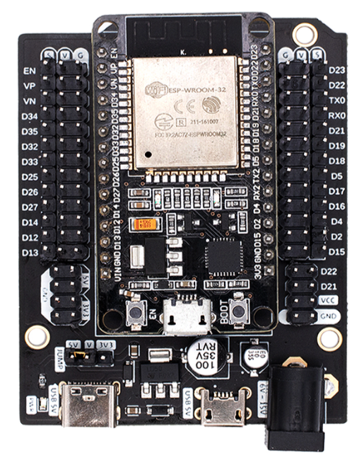
The ESP32+Shield (Manufacturer: NodeMCU, Part ID: V3) is a versatile microcontroller module designed for Internet of Things (IoT) applications. The ESP32 microcontroller features integrated Wi-Fi and Bluetooth capabilities, making it ideal for wireless communication and smart device projects. The accompanying shield enhances the functionality of the ESP32 by providing additional features such as sensors, connectors, and power management, simplifying the development process for users.
Explore Projects Built with Esp32+Shield
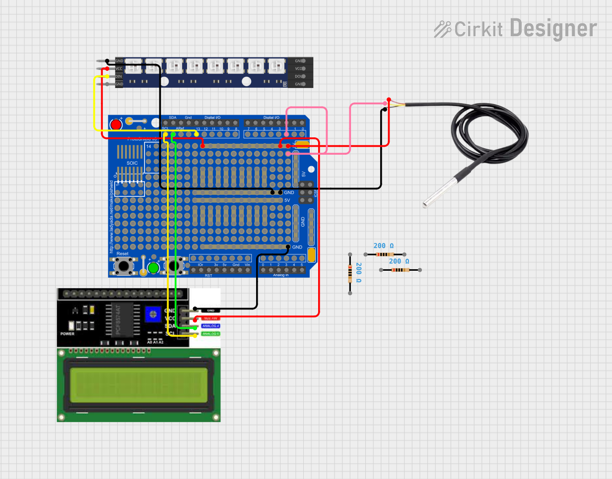


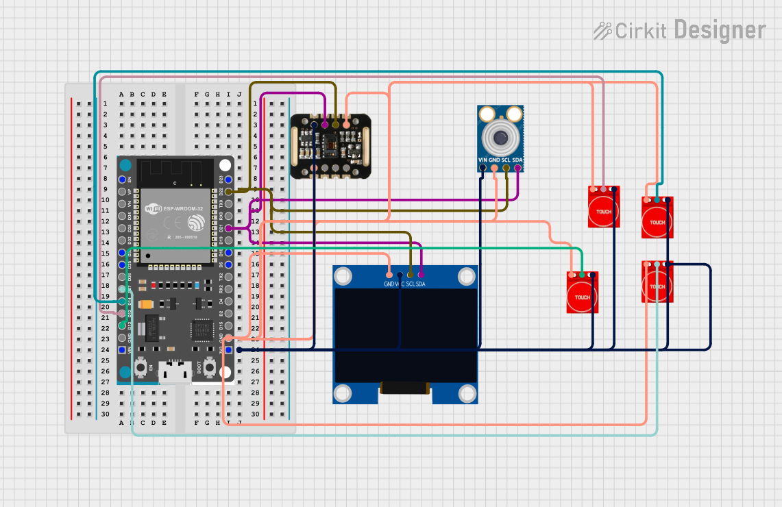
Explore Projects Built with Esp32+Shield
Common Applications and Use Cases
- Home automation systems
- Wireless sensor networks
- Smart appliances
- Industrial IoT applications
- Wearable devices
- Robotics and automation projects
Technical Specifications
Key Technical Details
| Parameter | Specification |
|---|---|
| Microcontroller | ESP32 (dual-core, 32-bit LX6 microprocessor) |
| Clock Speed | Up to 240 MHz |
| Flash Memory | 4 MB (varies by model) |
| SRAM | 520 KB |
| Wireless Connectivity | Wi-Fi 802.11 b/g/n, Bluetooth 4.2 (Classic + BLE) |
| Operating Voltage | 3.3V |
| Input Voltage (Shield) | 5V (via USB or external power supply) |
| GPIO Pins | 30+ (varies by shield design) |
| ADC Channels | Up to 18 |
| PWM Channels | 16 |
| Communication Interfaces | UART, SPI, I2C, I2S, CAN, Ethernet MAC |
| Power Management | Integrated voltage regulator on the shield |
Pin Configuration and Descriptions
The ESP32+Shield typically includes a pinout that combines the ESP32's GPIO pins with additional features provided by the shield. Below is a general pin configuration:
| Pin Name | Description |
|---|---|
| VIN | Input voltage (5V) for powering the shield and ESP32 |
| 3V3 | 3.3V output from the onboard regulator |
| GND | Ground connection |
| GPIO0-39 | General-purpose input/output pins |
| ADC1/ADC2 | Analog-to-digital converter pins |
| TX/RX | UART communication pins |
| SCL/SDA | I2C clock and data lines |
| MOSI/MISO | SPI data lines |
| EN | Enable pin for the ESP32 |
| RST | Reset pin |
Note: The exact pinout may vary depending on the shield design. Refer to the specific shield's datasheet for detailed pin mappings.
Usage Instructions
How to Use the ESP32+Shield in a Circuit
Powering the Module:
- Connect the shield to a 5V power source via the USB port or VIN pin. The onboard voltage regulator will step down the voltage to 3.3V for the ESP32.
- Ensure the power supply can provide sufficient current (at least 500mA) for stable operation.
Connecting Peripherals:
- Use the GPIO pins to connect sensors, actuators, or other peripherals. Ensure the voltage levels are compatible with the ESP32's 3.3V logic.
- For analog sensors, connect them to the ADC pins (e.g., ADC1 or ADC2).
Programming the ESP32:
- Install the ESP32 board package in the Arduino IDE or use the ESP-IDF (Espressif IoT Development Framework) for advanced programming.
- Connect the ESP32+Shield to your computer via USB and select the appropriate COM port in the IDE.
Uploading Code:
- Write your code in the Arduino IDE or ESP-IDF and upload it to the ESP32. Ensure the correct board and port are selected in the IDE settings.
Important Considerations and Best Practices
- Voltage Levels: Avoid applying voltages higher than 3.3V to the GPIO pins to prevent damage to the ESP32.
- Power Supply: Use a stable power source to avoid unexpected resets or malfunctions.
- Wi-Fi Interference: Place the ESP32+Shield away from sources of electromagnetic interference for optimal Wi-Fi performance.
- Heat Management: The ESP32 may heat up during operation. Ensure adequate ventilation or use a heatsink if necessary.
Example Code for Arduino UNO Integration
Below is an example of how to use the ESP32+Shield to read data from a DHT11 temperature and humidity sensor and send it to a serial monitor:
#include <WiFi.h>
#include <DHT.h>

// Define DHT sensor type and pin
#define DHTPIN 4       // GPIO pin connected to the DHT sensor
#define DHTTYPE DHT11  // DHT11 sensor type

DHT dht(DHTPIN, DHTTYPE);

void setup() {
  Serial.begin(115200);  // Initialize serial communication
  dht.begin();           // Initialize the DHT sensor
  Serial.println("ESP32+Shield: DHT11 Sensor Example");
}

void loop() {
  // Read temperature and humidity from the DHT sensor
  float humidity = dht.readHumidity();
  float temperature = dht.readTemperature();

  // Check if the readings are valid
  if (isnan(humidity) || isnan(temperature)) {
    Serial.println("Failed to read from DHT sensor!");
    return;
  }

  // Print the readings to the serial monitor
  Serial.print("Humidity: ");
  Serial.print(humidity);
  Serial.print("%, Temperature: ");
  Serial.print(temperature);
  Serial.println("°C");

  delay(2000);  // Wait 2 seconds before the next reading
}
Note: Replace
DHTPINwith the GPIO pin connected to your DHT sensor. Ensure the DHT library is installed in your Arduino IDE.
Troubleshooting and FAQs
Common Issues and Solutions
ESP32 Not Detected by Computer:
- Ensure the USB cable is functional and supports data transfer.
- Install the correct USB-to-serial driver for the ESP32 (e.g., CP210x or CH340).
Code Upload Fails:
- Check that the correct board and COM port are selected in the Arduino IDE.
- Press and hold the "BOOT" button on the ESP32 while uploading the code.
Wi-Fi Connection Issues:
- Verify the SSID and password in your code.
- Ensure the Wi-Fi network is within range and not overloaded.
Unstable Operation:
- Use a stable power supply with sufficient current capacity.
- Check for loose connections or short circuits in your circuit.
FAQs
Q: Can I use 5V sensors with the ESP32+Shield?
A: Yes, but you will need a level shifter to step down the 5V signal to 3.3V for the ESP32's GPIO pins.
Q: How do I reset the ESP32?
A: Press the "RST" button on the shield to reset the ESP32.
Q: Can I use the ESP32+Shield with other development environments?
A: Yes, the ESP32 is compatible with the ESP-IDF, MicroPython, and other development platforms.
Q: What is the maximum Wi-Fi range of the ESP32?
A: The range depends on environmental factors but typically extends up to 50 meters indoors and 200 meters outdoors.