How to Use DVP12SE: Examples, Pinouts, and Specs
Introduction
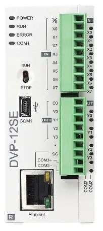
The DVP12SE, manufactured by Delta, is a high-performance digital video processor (part ID: PLC) designed for professional video signal processing applications. It features advanced capabilities such as scaling, deinterlacing, and color correction, ensuring superior video quality. This component is ideal for use in broadcast systems, video walls, surveillance systems, and other professional video applications where high-quality signal processing is critical.
Explore Projects Built with DVP12SE
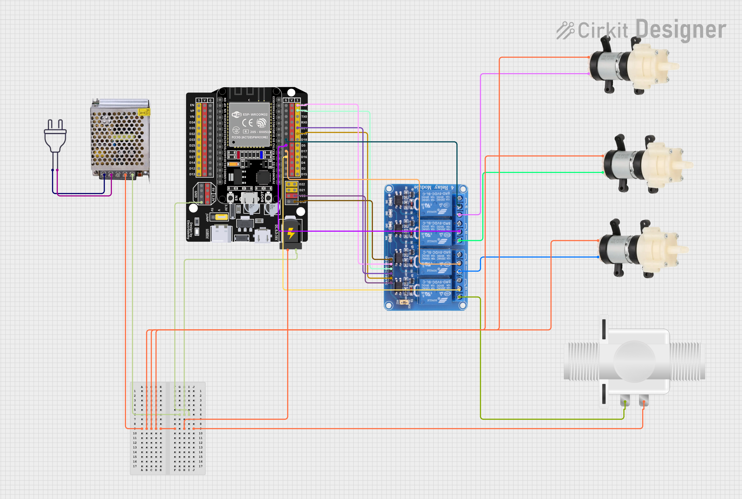


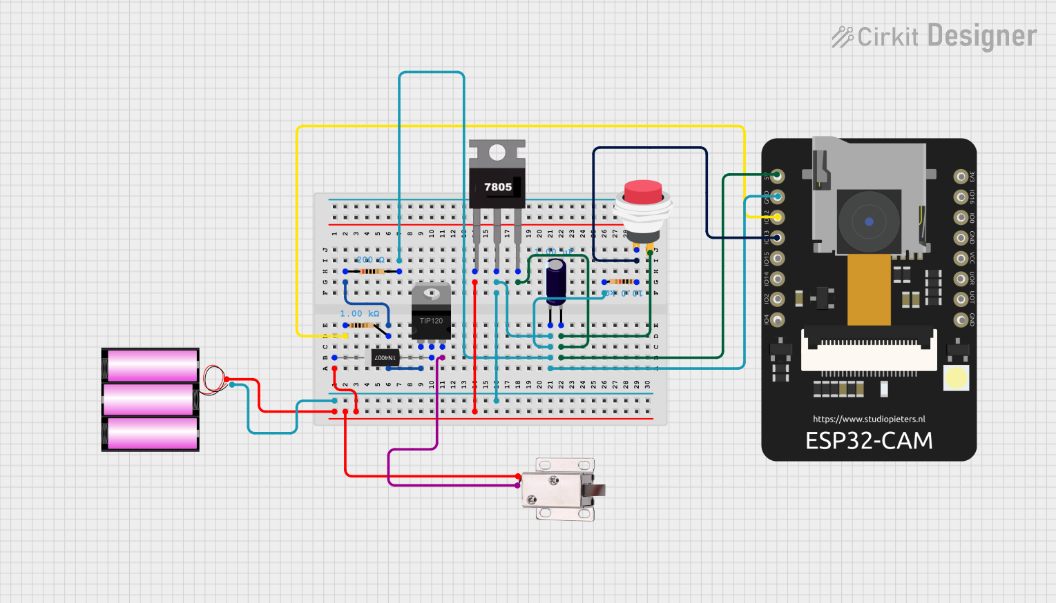
Explore Projects Built with DVP12SE
Common Applications
- Broadcast and production studios
- Video wall controllers
- Surveillance and security systems
- High-definition video playback and processing
- Professional AV systems
Technical Specifications
Key Technical Details
| Parameter | Value |
|---|---|
| Manufacturer | Delta |
| Part ID | PLC |
| Input Voltage Range | 3.3V to 5V |
| Power Consumption | < 2W |
| Video Input Formats | HDMI, DVI, VGA, Component, Composite |
| Video Output Formats | HDMI, DVI |
| Maximum Resolution | 4K UHD (3840 x 2160) @ 60Hz |
| Processing Features | Scaling, deinterlacing, color correction |
| Operating Temperature | -10°C to 70°C |
| Storage Temperature | -40°C to 85°C |
| Dimensions | 50mm x 50mm x 10mm |
Pin Configuration and Descriptions
The DVP12SE features a 20-pin interface for power, control, and video signal connections. Below is the pin configuration:
| Pin Number | Pin Name | Description |
|---|---|---|
| 1 | VCC | Power supply input (3.3V to 5V) |
| 2 | GND | Ground |
| 3 | HDMI_IN | HDMI video input |
| 4 | DVI_IN | DVI video input |
| 5 | VGA_IN | VGA video input |
| 6 | COMP_IN | Component video input |
| 7 | COMPOSITE_IN | Composite video input |
| 8 | HDMI_OUT | HDMI video output |
| 9 | DVI_OUT | DVI video output |
| 10 | I2C_SCL | I2C clock for control interface |
| 11 | I2C_SDA | I2C data for control interface |
| 12 | RESET | Reset pin (active low) |
| 13 | STATUS_LED | Status indicator output |
| 14 | CLK_IN | External clock input |
| 15 | SYNC_OUT | Synchronization signal output |
| 16 | AUDIO_IN | Audio input for HDMI embedding |
| 17 | AUDIO_OUT | Audio output from HDMI extraction |
| 18 | TEST_MODE | Test mode activation pin |
| 19 | NC | Not connected |
| 20 | NC | Not connected |
Usage Instructions
How to Use the DVP12SE in a Circuit
- Power Supply: Connect the VCC pin to a regulated 3.3V to 5V power source and the GND pin to ground.
- Video Input: Connect the desired video input source (e.g., HDMI, DVI, VGA) to the corresponding input pin.
- Video Output: Connect the HDMI_OUT or DVI_OUT pin to the display or video processing device.
- Control Interface: Use the I2C_SCL and I2C_SDA pins to configure the DVP12SE via an I2C-compatible microcontroller or processor.
- Reset: Connect the RESET pin to a microcontroller GPIO for manual or automatic reset functionality.
- Audio Handling: Use the AUDIO_IN and AUDIO_OUT pins for embedding or extracting audio signals in HDMI streams.
Important Considerations and Best Practices
- Ensure the power supply is stable and within the specified voltage range to avoid damage to the component.
- Use proper shielding and grounding techniques to minimize noise and interference in video signals.
- For I2C communication, use appropriate pull-up resistors on the SCL and SDA lines.
- Avoid leaving unused input pins floating; connect them to ground or a defined logic level.
- Use a heatsink or active cooling if the component operates in high-temperature environments or under heavy processing loads.
Example: Connecting the DVP12SE to an Arduino UNO
The DVP12SE can be controlled via I2C using an Arduino UNO. Below is an example code snippet to configure the DVP12SE:
#include <Wire.h> // Include the Wire library for I2C communication

#define DVP12SE_I2C_ADDRESS 0x40 // Replace with the actual I2C address of the DVP12SE

void setup() {
  Wire.begin(); // Initialize I2C communication
  Serial.begin(9600); // Initialize serial communication for debugging

  // Configure the DVP12SE
  Wire.beginTransmission(DVP12SE_I2C_ADDRESS);
  Wire.write(0x01); // Example register address for configuration
  Wire.write(0x80); // Example value to set the register
  Wire.endTransmission();

  Serial.println("DVP12SE configured successfully.");
}

void loop() {
  // Monitor the status of the DVP12SE
  Wire.beginTransmission(DVP12SE_I2C_ADDRESS);
  Wire.write(0x02); // Example register address for status
  Wire.endTransmission();

  Wire.requestFrom(DVP12SE_I2C_ADDRESS, 1);
  if (Wire.available()) {
    byte status = Wire.read();
    Serial.print("DVP12SE Status: ");
    Serial.println(status, HEX);
  }

  delay(1000); // Wait for 1 second before checking again
}
Troubleshooting and FAQs
Common Issues and Solutions
No Video Output:
- Ensure the input video source is connected to the correct input pin.
- Verify that the output display is connected to the correct output pin.
- Check the power supply and ensure the component is powered correctly.
I2C Communication Fails:
- Verify the I2C address of the DVP12SE and ensure it matches the address in your code.
- Check the pull-up resistors on the SCL and SDA lines.
- Ensure the Arduino or microcontroller is properly initialized for I2C communication.
Overheating:
- Ensure adequate ventilation or cooling for the DVP12SE.
- Check for excessive power consumption or incorrect input signals.
Audio Issues:
- Verify the AUDIO_IN and AUDIO_OUT connections.
- Ensure the audio format is compatible with the DVP12SE.
FAQs
Q: Can the DVP12SE process 4K video at 120Hz?
A: No, the DVP12SE supports a maximum resolution of 4K UHD (3840 x 2160) at 60Hz.
Q: Is the DVP12SE compatible with analog video sources?
A: Yes, the DVP12SE supports component and composite video inputs for analog sources.
Q: Can I use the DVP12SE without an I2C controller?
A: Basic functionality may work without I2C configuration, but advanced features require I2C control.
Q: What is the purpose of the TEST_MODE pin?
A: The TEST_MODE pin is used for factory testing and diagnostics. It is not required for normal operation.