How to Use LCD screen: Examples, Pinouts, and Specs
Introduction
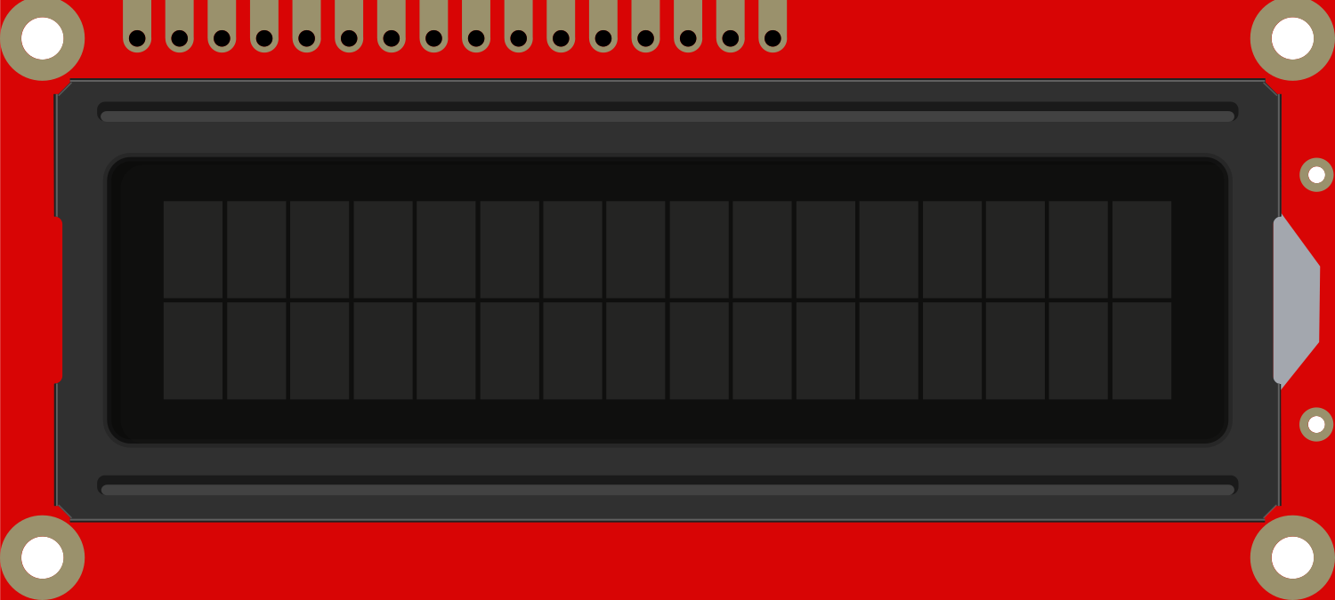
An LCD (Liquid Crystal Display) screen is a type of flat-panel display which uses the light-modulating properties of liquid crystals combined with polarizers. Liquid crystals do not emit light directly, instead using a backlight or reflector to produce images in color or monochrome. LCDs are available in a range of sizes and are common in a variety of devices including calculators, watches, laptops, smartphones, and digital signage.
Explore Projects Built with LCD screen

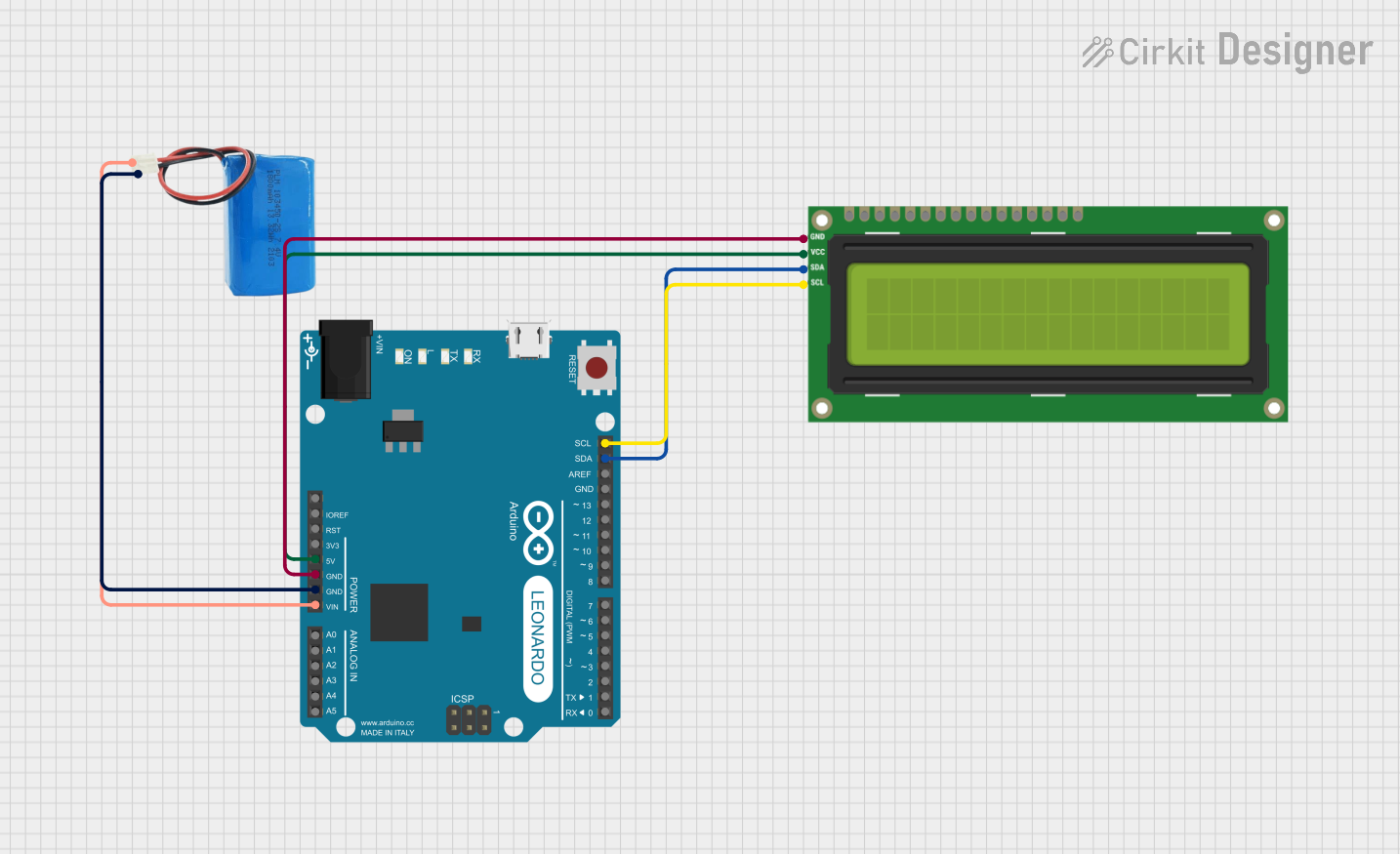
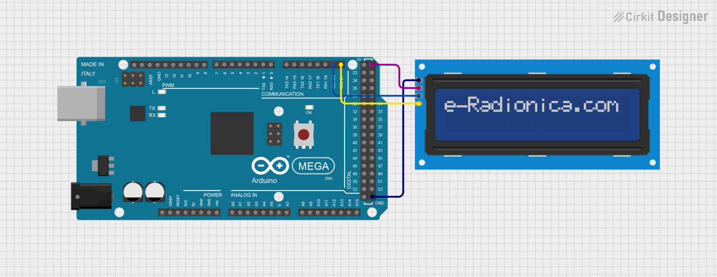
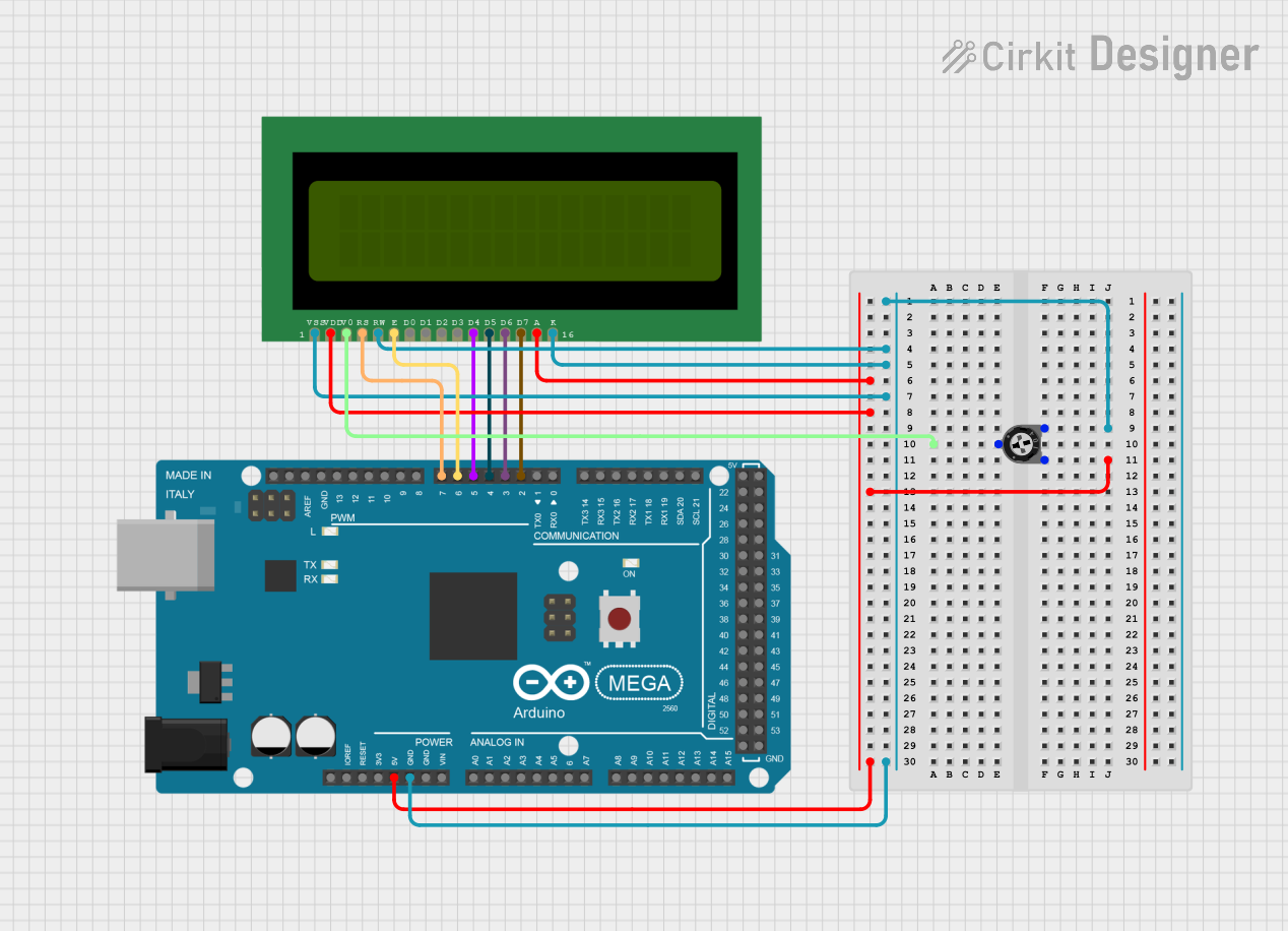
Explore Projects Built with LCD screen
Common Applications and Use Cases
- Consumer Electronics: Smartphones, TVs, computer monitors, and digital clocks.
- Automotive Displays: Dashboard information displays, GPS, and entertainment systems.
- Industrial Controls: User interface panels for machinery and equipment.
- Medical Equipment: Displays for monitoring devices and diagnostic equipment.
- Portable Devices: Handheld gaming devices, e-readers, and tablets.
Technical Specifications
Key Technical Details
- Display Type: TFT, IPS, or TN typically
- Resolution: Varies (e.g., 128x64, 320x240, 800x480 pixels)
- Operating Voltage: Typically 3.3V or 5V
- Interface: Parallel, Serial (SPI/I2C), or RGB
- Backlight: LED
- Viewing Angle: Varies with technology; TN has the narrowest, IPS the widest
- Contrast Ratio: Varies with technology and quality
- Response Time: Varies, important for video or fast-moving graphics
Pin Configuration and Descriptions
| Pin Number | Name | Description |
|---|---|---|
| 1 | VSS | Ground |
| 2 | VDD | Power supply (3.3V or 5V) |
| 3 | VO | Contrast adjustment |
| 4 | RS | Register select signal |
| 5 | R/W | Read/Write signal |
| 6 | E | Enable signal |
| 7-14 | D0-D7 | Data bus for 8-bit mode |
| 15 | LED+ | Anode for LED backlight |
| 16 | LED- | Cathode for LED backlight |
Note: The pin configuration may vary depending on the specific model and interface of the LCD.
Usage Instructions
How to Use the Component in a Circuit
- Power Connections: Connect VSS to ground and VDD to your power supply (3.3V or 5V depending on your LCD).
- Data Interface: Connect the data pins (D0-D7 for 8-bit mode) to the microcontroller's digital pins if using parallel communication.
- Control Pins: Connect RS, R/W, and E to the microcontroller's digital pins.
- Contrast Adjustment: Connect VO to a potentiometer for contrast adjustment.
- Backlight: Connect LED+ and LED- to power and ground respectively, with a current-limiting resistor in series if necessary.
Important Considerations and Best Practices
- Power Supply: Ensure that the voltage levels match the LCD's requirements.
- Contrast: Adjust the contrast potentiometer for clear visibility.
- Data Modes: Use 4-bit mode to save microcontroller pins if needed.
- Backlight: Use a current-limiting resistor to prevent damage to the LED backlight.
- Library Use: Utilize libraries for interfacing with the LCD to simplify code.
Example Arduino UNO Code
#include <LiquidCrystal.h>

// Initialize the library with the numbers of the interface pins
LiquidCrystal lcd(12, 11, 5, 4, 3, 2);

void setup() {
  // Set up the LCD's number of columns and rows:
  lcd.begin(16, 2);
  // Print a message to the LCD.
  lcd.print("Hello, World!");
}

void loop() {
  // Set the cursor to column 0, line 1
  // (note: line 1 is the second row, since counting begins with 0):
  lcd.setCursor(0, 1);
  // Print the number of seconds since reset:
  lcd.print(millis() / 1000);
}
Note: The above code assumes a 16x2 LCD screen. Adjust the lcd.begin() parameters according to your LCD's specifications.
Troubleshooting and FAQs
Common Issues
- Display is Blank: Check the contrast adjustment. If the contrast is too low, the display will appear blank.
- Garbled Characters: Ensure that all data and control lines are properly connected and that there are no loose connections.
- No Backlight: Verify that the LED+ and LED- pins are correctly connected with the appropriate current-limiting resistor.
Solutions and Tips for Troubleshooting
- Contrast Adjustment: Turn the potentiometer slowly while the LCD is powered until the text becomes visible.
- Check Connections: Re-seat all connections and ensure that solder joints are solid and not causing shorts.
- Code Verification: Double-check the pin assignments in your code to ensure they match the physical connections.
FAQs
Q: Can I use the LCD with a 3.3V system? A: Yes, but ensure that the LCD is compatible with 3.3V operation and adjust the contrast accordingly.
Q: How do I know if my LCD is in 4-bit or 8-bit mode? A: This is determined by how you wire the LCD to your microcontroller and how you initialize it in your code.
Q: Can I display graphics on an alphanumeric LCD? A: Alphanumeric LCDs are limited to characters and custom-created glyphs. For full graphics, use a graphical LCD.
Q: Why is my LCD displaying random characters? A: This could be due to noise, incorrect initialization, or a faulty LCD. Check your wiring and try resetting the power to the LCD.
This documentation provides a comprehensive guide to using an LCD screen with an Arduino UNO or similar microcontroller. For specific models or advanced features, refer to the datasheet of your particular LCD module.