How to Use ESP32-CAM-MB: Examples, Pinouts, and Specs
Introduction
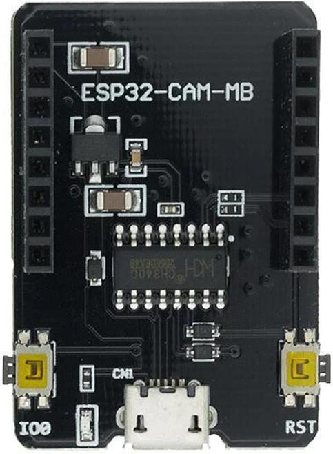
The ESP32-CAM-MB, manufactured by Aman Yadav, is a compact development board that integrates the powerful ESP32 chip with built-in Wi-Fi and Bluetooth capabilities. It also features a camera module, making it an ideal choice for IoT applications that require image capture, video streaming, or remote monitoring. The board is designed to simplify the development of smart devices, offering a cost-effective and versatile solution for projects involving wireless communication and visual data processing.
Explore Projects Built with ESP32-CAM-MB


Explore Projects Built with ESP32-CAM-MB
Common Applications and Use Cases
- Smart home security systems
- Wireless video streaming and surveillance
- IoT-enabled image recognition and processing
- Remote monitoring and control systems
- DIY robotics with vision capabilities
- Environmental monitoring with visual data logging
Technical Specifications
The ESP32-CAM-MB combines the ESP32 microcontroller with a camera module and USB-to-serial interface for easy programming. Below are the key technical details:
Key Features
- Microcontroller: ESP32 (dual-core, 32-bit LX6 processor)
- Wireless Connectivity: Wi-Fi 802.11 b/g/n and Bluetooth 4.2 (BLE)
- Camera Module: OV2640 (2MP resolution)
- Flash Memory: 4MB (SPI Flash)
- RAM: 520KB SRAM + 4MB PSRAM
- Operating Voltage: 3.3V
- Power Supply: 5V via micro-USB or external source
- GPIO Pins: 9 available for user applications
- Interfaces: UART, SPI, I2C, PWM
- Dimensions: 27mm x 40.5mm
Pin Configuration and Descriptions
The ESP32-CAM-MB has a compact pinout. Below is the pin configuration:
| Pin Name | Description |
|---|---|
| GND | Ground |
| 3.3V | 3.3V power output |
| 5V | 5V power input |
| GPIO0 | General-purpose I/O, used for boot mode |
| GPIO1 | UART TX (serial communication) |
| GPIO3 | UART RX (serial communication) |
| GPIO12 | General-purpose I/O |
| GPIO13 | General-purpose I/O |
| GPIO14 | General-purpose I/O |
| GPIO15 | General-purpose I/O |
| GPIO16 | General-purpose I/O |
| GPIO33 | General-purpose I/O |
| RESET | Reset pin |
Usage Instructions
The ESP32-CAM-MB is easy to set up and use for IoT projects. Follow the steps below to get started:
Setting Up the ESP32-CAM-MB
Install the Arduino IDE:
- Download and install the Arduino IDE from the official website.
- Add the ESP32 board support package by navigating to
File > Preferencesand adding the following URL to the "Additional Board Manager URLs" field:https://dl.espressif.com/dl/package_esp32_index.json - Go to
Tools > Board > Boards Manager, search for "ESP32," and install the package.
Connect the ESP32-CAM-MB:
- Use a micro-USB cable to connect the ESP32-CAM-MB to your computer.
- Ensure the board is in programming mode by connecting GPIO0 to GND before powering it on.
Select the Board and Port:
- In the Arduino IDE, go to
Tools > Boardand select "AI Thinker ESP32-CAM." - Under
Tools > Port, select the COM port associated with your ESP32-CAM-MB.
- In the Arduino IDE, go to
Upload Code:
- Write or load your desired sketch in the Arduino IDE.
- Click the upload button to program the board. Once the upload is complete, disconnect GPIO0 from GND and reset the board.
Example Code: Capturing and Streaming Video
The following example demonstrates how to set up the ESP32-CAM-MB for video streaming:
#include <WiFi.h>
#include "esp_camera.h"

// Replace with your Wi-Fi credentials
const char* ssid = "Your_SSID";
const char* password = "Your_PASSWORD";

// Camera configuration
#define PWDN_GPIO_NUM    -1
#define RESET_GPIO_NUM   -1
#define XCLK_GPIO_NUM     0
#define SIOD_GPIO_NUM    26
#define SIOC_GPIO_NUM    27
#define Y9_GPIO_NUM      35
#define Y8_GPIO_NUM      34
#define Y7_GPIO_NUM      39
#define Y6_GPIO_NUM      36
#define Y5_GPIO_NUM      21
#define Y4_GPIO_NUM      19
#define Y3_GPIO_NUM      18
#define Y2_GPIO_NUM       5
#define VSYNC_GPIO_NUM   25
#define HREF_GPIO_NUM    23
#define PCLK_GPIO_NUM    22

void startCameraServer();

void setup() {
  Serial.begin(115200);
  WiFi.begin(ssid, password);

  // Wait for Wi-Fi connection
  while (WiFi.status() != WL_CONNECTED) {
    delay(500);
    Serial.print(".");
  }
  Serial.println("");
  Serial.println("Wi-Fi connected");
  Serial.println(WiFi.localIP());

  // Initialize the camera
  camera_config_t config;
  config.ledc_channel = LEDC_CHANNEL_0;
  config.ledc_timer = LEDC_TIMER_0;
  config.pin_d0 = Y2_GPIO_NUM;
  config.pin_d1 = Y3_GPIO_NUM;
  config.pin_d2 = Y4_GPIO_NUM;
  config.pin_d3 = Y5_GPIO_NUM;
  config.pin_d4 = Y6_GPIO_NUM;
  config.pin_d5 = Y7_GPIO_NUM;
  config.pin_d6 = Y8_GPIO_NUM;
  config.pin_d7 = Y9_GPIO_NUM;
  config.pin_xclk = XCLK_GPIO_NUM;
  config.pin_pclk = PCLK_GPIO_NUM;
  config.pin_vsync = VSYNC_GPIO_NUM;
  config.pin_href = HREF_GPIO_NUM;
  config.pin_sscb_sda = SIOD_GPIO_NUM;
  config.pin_sscb_scl = SIOC_GPIO_NUM;
  config.pin_pwdn = PWDN_GPIO_NUM;
  config.pin_reset = RESET_GPIO_NUM;
  config.xclk_freq_hz = 20000000;
  config.pixel_format = PIXFORMAT_JPEG;

  if (psramFound()) {
    config.frame_size = FRAMESIZE_UXGA;
    config.jpeg_quality = 10;
    config.fb_count = 2;
  } else {
    config.frame_size = FRAMESIZE_SVGA;
    config.jpeg_quality = 12;
    config.fb_count = 1;
  }

  // Start the camera
  esp_err_t err = esp_camera_init(&config);
  if (err != ESP_OK) {
    Serial.printf("Camera init failed with error 0x%x", err);
    return;
  }

  // Start the web server
  startCameraServer();
}

void loop() {
  // Main loop does nothing; camera server handles requests
}
Important Considerations
- Ensure the ESP32-CAM-MB is powered with a stable 5V supply to avoid brownout issues.
- Use a heat sink if the board gets too hot during operation.
- For programming, always connect GPIO0 to GND and reset the board after uploading the code.
Troubleshooting and FAQs
Common Issues
Camera Initialization Failed:
- Ensure the camera module is properly connected to the board.
- Verify the camera configuration in the code matches the hardware.
Wi-Fi Connection Issues:
- Double-check the SSID and password in your code.
- Ensure the Wi-Fi network is within range and not overloaded.
Serial Port Not Detected:
- Confirm the USB cable is functional and supports data transfer.
- Check if the correct COM port is selected in the Arduino IDE.
Solutions and Tips
- If the board fails to boot, try using a different power source or USB cable.
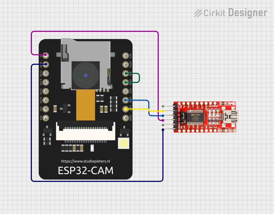
- Use a dedicated FTDI programmer if the onboard USB-to-serial interface is not working.
- For better performance, use a lower resolution or frame rate when streaming video.
This concludes the documentation for the ESP32-CAM-MB. Happy building!