
How to Use MY2N: Examples, Pinouts, and Specs
 Design with MY2N in Cirkit Designer
Introduction
The MY2N is a relay component manufactured by SMKN 2 PAS with the part ID 03. It is a versatile and reliable relay designed for switching applications in electronic circuits. Featuring a double pole, double throw (DPDT) configuration, the MY2N can control two independent circuits simultaneously. The relay operates using an electromagnetic coil, which activates the switching mechanism when an appropriate input signal is applied.
Explore Projects Built with MY2N
 Open Project in Cirkit Designer
 Open Project in Cirkit Designer
 Open Project in Cirkit Designer
 Open Project in Cirkit Designer
Explore Projects Built with MY2N
Open Project in Cirkit DesignerOpen Project in Cirkit DesignerOpen Project in Cirkit DesignerOpen Project in Cirkit DesignerCommon Applications and Use Cases
- Industrial automation systems
- Home appliances
- Motor control circuits
- Signal switching in communication systems
- Power management in electronic devices
Technical Specifications
Key Technical Details
| Parameter | Value |
|---|---|
| Manufacturer | SMKN 2 PAS |
| Part ID | 03 |
| Relay Type | Electromagnetic Relay |
| Configuration | DPDT (Double Pole, Double Throw) |
| Coil Voltage | 12V DC (typical) |
| Coil Resistance | 160 Ω |
| Contact Rating | 5A at 250V AC / 30V DC |
| Switching Voltage | Max 250V AC / 125V DC |
| Switching Current | Max 5A |
| Insulation Resistance | ≥ 100 MΩ at 500V DC |
| Operating Temperature | -40°C to +70°C |
| Mechanical Life | 10 million operations |
| Electrical Life | 100,000 operations |
Pin Configuration and Descriptions
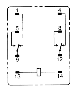
The MY2N relay has 8 pins, which are configured as follows:
| Pin Number | Description |
|---|---|
| 1 | Coil Terminal 1 (Positive) |
| 2 | Coil Terminal 2 (Negative) |
| 3 | Common Terminal for Pole 1 |
| 4 | Normally Closed (NC) for Pole 1 |
| 5 | Normally Open (NO) for Pole 1 |
| 6 | Common Terminal for Pole 2 |
| 7 | Normally Closed (NC) for Pole 2 |
| 8 | Normally Open (NO) for Pole 2 |
Usage Instructions
How to Use the MY2N in a Circuit
- Power the Coil: Connect the coil terminals (pins 1 and 2) to a 12V DC power source. Ensure the polarity is correct.
- Connect the Load:
- For Pole 1, connect the load to the common terminal (pin 3) and either the normally closed (pin 4) or normally open (pin 5) terminal, depending on the desired behavior.
- For Pole 2, connect the load to the common terminal (pin 6) and either the normally closed (pin 7) or normally open (pin 8) terminal.
- Control the Relay: Apply a control signal to the coil terminals to activate the relay. When the coil is energized, the normally open contacts close, and the normally closed contacts open.
Important Considerations and Best Practices
- Diode Protection: Place a flyback diode across the coil terminals to protect the circuit from voltage spikes when the relay is de-energized.
- Current Rating: Ensure the load current does not exceed the relay's maximum contact rating of 5A.
- Isolation: Use optocouplers or transistors to isolate the control circuit from the relay if necessary.
- Mounting: Secure the relay in a socket or PCB to prevent mechanical stress.
Example: Using MY2N with Arduino UNO
The MY2N relay can be easily controlled using an Arduino UNO. Below is an example circuit and code to toggle the relay:
Circuit Connections
- Connect pin 1 of the relay to the Arduino's digital pin 7 (via a transistor and resistor for current amplification).
- Connect pin 2 of the relay to the Arduino's GND.
- Connect the load to the relay's common and normally open terminals.
Arduino Code
// Define the relay control pin
const int relayPin = 7;

void setup() {
  pinMode(relayPin, OUTPUT); // Set relay pin as output
  digitalWrite(relayPin, LOW); // Ensure relay is off at startup
}

void loop() {
  digitalWrite(relayPin, HIGH); // Turn relay on
  delay(1000); // Keep relay on for 1 second
  digitalWrite(relayPin, LOW); // Turn relay off
  delay(1000); // Keep relay off for 1 second
}
Troubleshooting and FAQs
Common Issues and Solutions
Relay Not Activating:
- Check the coil voltage. Ensure it matches the specified 12V DC.
- Verify the connections to the coil terminals (pins 1 and 2).
- Inspect the control circuit for faults, such as incorrect wiring or insufficient current.
Contacts Not Switching:
- Ensure the load current does not exceed the relay's contact rating.
- Check for mechanical damage or wear on the relay contacts.
Voltage Spikes in the Circuit:
- Install a flyback diode across the coil terminals to suppress voltage spikes.
Relay Buzzing or Chattering:
- Verify that the control signal is stable and free from noise.
- Ensure the power supply provides sufficient current to the coil.
FAQs
Q: Can the MY2N relay handle AC loads?
A: Yes, the MY2N can handle AC loads up to 250V with a maximum current of 5A.
Q: What is the purpose of the DPDT configuration?
A: The DPDT configuration allows the relay to control two independent circuits simultaneously, providing flexibility in switching applications.
Q: How do I extend the relay's lifespan?
A: Operate the relay within its specified ratings, use proper protection circuits (e.g., flyback diodes), and avoid excessive mechanical stress during installation.
Q: Can I use the MY2N with a 5V control signal?
A: No, the MY2N requires a 12V DC signal to activate the coil. Use a transistor or relay driver circuit to step up the control voltage if needed.