How to Use Pmod OLEDrgb: Examples, Pinouts, and Specs
Introduction
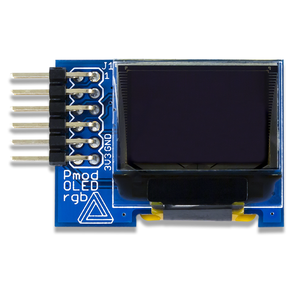
The Pmod OLEDrgb, manufactured by Digilent, is a versatile Pmod interface module featuring a full-color RGB OLED display. This module allows users to visualize graphics and text with high contrast and low power consumption, making it ideal for applications requiring compact, vibrant displays. The Pmod OLEDrgb is based on the SSD1331 OLED driver, which provides advanced control over the display's color and brightness.
Explore Projects Built with Pmod OLEDrgb

Explore Projects Built with Pmod OLEDrgb
Common Applications
- Embedded systems requiring graphical user interfaces
- Wearable devices with compact displays
- Educational projects and prototyping
- Low-power IoT devices with visual feedback
- Portable diagnostic or monitoring tools
Technical Specifications
The Pmod OLEDrgb is designed to interface seamlessly with microcontrollers and FPGAs via SPI communication. Below are the key technical details:
Key Specifications
| Parameter | Value |
|---|---|
| Display Type | RGB OLED |
| Resolution | 96 x 64 pixels |
| Color Depth | 65,536 colors (16-bit) |
| Communication Protocol | SPI |
| Supply Voltage | 3.3V |
| Power Consumption | Low (varies with brightness) |
| Dimensions | 1.6" x 0.8" (40.6mm x 20.3mm) |
Pin Configuration
The Pmod OLEDrgb uses a 12-pin connector for interfacing. The pinout is as follows:
| Pin Number | Pin Name | Description |
|---|---|---|
| 1 | GND | Ground |
| 2 | VCC | Power supply (3.3V) |
| 3 | SCL | SPI Clock |
| 4 | SDA | SPI Data |
| 5 | RES | Reset signal |
| 6 | DC | Data/Command select |
| 7 | CS | Chip Select |
| 8 | NC | Not Connected |
| 9-12 | NC | Not Connected |
Usage Instructions
The Pmod OLEDrgb is straightforward to use in embedded systems. Below are the steps to integrate it into your project:
Connecting the Pmod OLEDrgb
- Power Supply: Connect the
VCCpin to a 3.3V power source and theGNDpin to ground. - SPI Interface: Connect the
SCL(SPI Clock),SDA(SPI Data),CS(Chip Select), andDC(Data/Command) pins to the corresponding SPI pins on your microcontroller or FPGA. - Reset Signal: Connect the
RESpin to a GPIO pin on your microcontroller for resetting the display.
Example Code for Arduino UNO
Below is an example of how to use the Pmod OLEDrgb with an Arduino UNO. Note that the Arduino UNO operates at 5V logic, so a level shifter is required to interface with the 3.3V Pmod OLEDrgb.
#include <SPI.h>

// Pin definitions for the Pmod OLEDrgb
#define CS_PIN 10   // Chip Select pin
#define DC_PIN 9    // Data/Command pin
#define RES_PIN 8   // Reset pin

void setup() {
  // Initialize SPI communication
  SPI.begin();

  // Configure control pins as outputs
  pinMode(CS_PIN, OUTPUT);
  pinMode(DC_PIN, OUTPUT);
  pinMode(RES_PIN, OUTPUT);

  // Reset the display
  digitalWrite(RES_PIN, LOW);
  delay(10); // Hold reset low for 10ms
  digitalWrite(RES_PIN, HIGH);

  // Initialize the display (send initialization commands)
  initializeDisplay();
}

void loop() {
  // Example: Clear the screen and draw a red rectangle
  clearScreen();
  drawRectangle(10, 10, 50, 30, 0xF800); // Red color in 16-bit RGB565 format
}

void initializeDisplay() {
  // Send initialization commands to the SSD1331 driver
  digitalWrite(CS_PIN, LOW);
  digitalWrite(DC_PIN, LOW);
  SPI.transfer(0xAE); // Display OFF
  // Add other initialization commands as needed
  digitalWrite(CS_PIN, HIGH);
}

void clearScreen() {
  // Clear the display by filling it with black
  digitalWrite(CS_PIN, LOW);
  digitalWrite(DC_PIN, LOW);
  SPI.transfer(0x25); // Command to clear the screen
  digitalWrite(CS_PIN, HIGH);
}

void drawRectangle(uint8_t x, uint8_t y, uint8_t width, uint8_t height,
                   uint16_t color) {
  // Draw a rectangle on the display
  digitalWrite(CS_PIN, LOW);
  digitalWrite(DC_PIN, LOW);
  SPI.transfer(0x22); // Command to draw a rectangle
  SPI.transfer(x);    // X start
  SPI.transfer(y);    // Y start
  SPI.transfer(x + width - 1); // X end
  SPI.transfer(y + height - 1); // Y end
  SPI.transfer(color >> 11);    // Red (5 bits)
  SPI.transfer((color >> 5) & 0x3F); // Green (6 bits)
  SPI.transfer(color & 0x1F);   // Blue (5 bits)
  digitalWrite(CS_PIN, HIGH);
}
Best Practices
- Use a level shifter when interfacing with 5V logic devices like the Arduino UNO.
- Avoid prolonged exposure to static images to prevent OLED burn-in.
- Ensure proper power supply filtering to avoid noise affecting the display.
Troubleshooting and FAQs
Common Issues
Display Not Turning On
- Verify the power supply connections (
VCCandGND). - Ensure the
RESpin is toggled during initialization.
- Verify the power supply connections (
No Output on the Display
- Check the SPI connections (
SCL,SDA,CS, andDC). - Confirm that the SPI clock speed is within the supported range of the SSD1331.
- Check the SPI connections (
Distorted or Incorrect Colors
- Verify that the color data is sent in the correct RGB565 format.
- Check for loose or incorrect wiring.
Tips for Troubleshooting
- Use a logic analyzer to monitor SPI communication and verify that commands are sent correctly.
- Refer to the SSD1331 datasheet for detailed command descriptions and timing requirements.
- Test the display with a known working example to rule out hardware issues.
By following this documentation, you can effectively integrate the Pmod OLEDrgb into your projects and take full advantage of its vibrant display capabilities.