Cirkit Designer Logo
Cirkit Designer
Your all-in-one circuit design IDE
Home / 
Component Documentation

How to Use IDG1215: Examples, Pinouts, and Specs
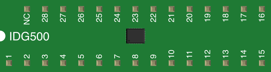

Image of IDG1215
Cirkit Designer LogoDesign with IDG1215 in Cirkit Designer

Introduction

The IDG1215 is a high-performance, low-power integrated circuit designed for applications requiring precise motion sensing and stabilization. It features a dual-axis MEMS gyroscope capable of delivering accurate angular rate measurements. This component is widely used in data acquisition, signal processing, and motion control systems. Its compact design and low power consumption make it ideal for portable devices, robotics, drones, and gaming controllers.

Explore Projects Built with IDG1215

Use Cirkit Designer to design, explore, and prototype these projects online. Some projects support real-time simulation. Click "Open Project" to start designing instantly!
Arduino Mega 2560 Based Security System with Fingerprint Authentication and SMS Alerts
Image of Door security system: A project utilizing IDG1215 in a practical application
This circuit features an Arduino Mega 2560 microcontroller interfaced with a SIM800L GSM module, two fingerprint scanners, an I2C LCD display, an IR sensor, and a piezo buzzer. Power management is handled by a PowerBoost 1000 Basic Pad USB, a TP4056 charging module, and a Li-ion 18650 battery, with an option to use a Mini AC-DC 110V-230V to 5V 700mA module for direct power supply. The primary functionality appears to be a security system with GSM communication capabilities, biometric access control, and visual/audible feedback.
Cirkit Designer LogoOpen Project in Cirkit Designer
Satellite-Based Timing and Navigation System with SDR and Atomic Clock Synchronization
Image of GPS 시스템 측정 구성도_Confirm: A project utilizing IDG1215 in a practical application
This circuit appears to be a complex system involving power supply management, GPS and timing synchronization, and data communication. It includes a SI-TEX G1 Satellite Compass for GPS data, an XHTF1021 Atomic Rubidium Clock for precise timing, and Ettus USRP B200 units for software-defined radio communication. Power is supplied through various SMPS units and distributed via terminal blocks and DC jacks. Data communication is facilitated by Beelink MINI S12 N95 computers, RS232 splitters, and a 1000BASE-T Media Converter for network connectivity. RF Directional Couplers are used to interface antennas with the USRP units, and the entire system is likely contained within cases for protection and organization.
Cirkit Designer LogoOpen Project in Cirkit Designer
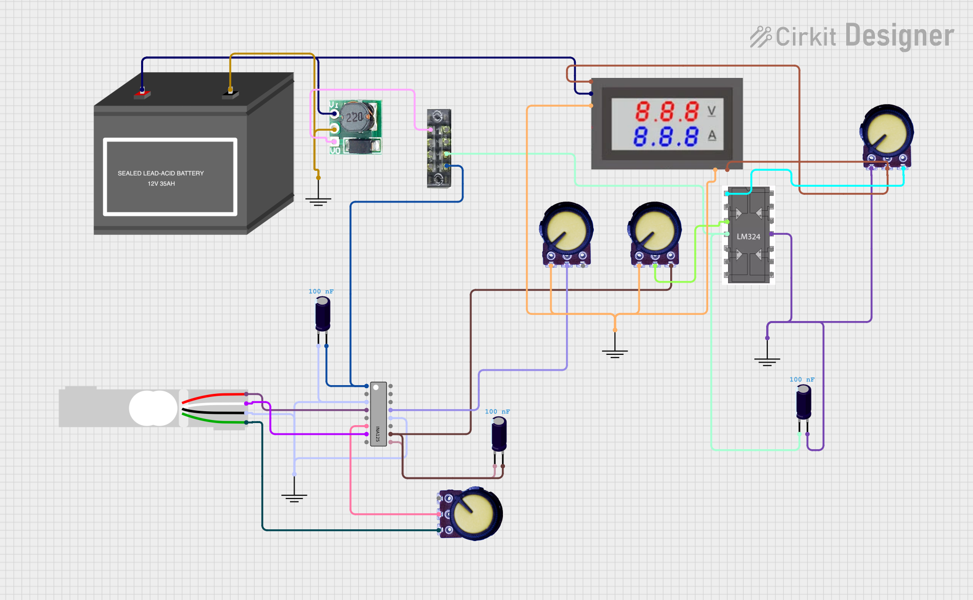
Battery-Powered Load Cell Amplifier with INA125 and LM324
Image of Test: A project utilizing IDG1215 in a practical application
This circuit is a load cell signal conditioning and amplification system. It uses an INA125 instrumentation amplifier to amplify the differential signal from a load cell, with additional filtering and gain control provided by potentiometers and capacitors. The amplified signal is then monitored by a digital voltmeter, and the entire system is powered by a 12V battery with a step-up boost converter to provide stable voltage.
Cirkit Designer LogoOpen Project in Cirkit Designer
Cellular-Enabled IoT Device with Real-Time Clock and Power Management
Image of LRCM PHASE 2 BASIC: A project utilizing IDG1215 in a practical application
This circuit features a LilyGo-SIM7000G module for cellular communication and GPS functionality, interfaced with an RTC DS3231 for real-time clock capabilities. It includes voltage sensing through two voltage sensor modules, and uses an 8-channel opto-coupler for isolating different parts of the circuit. Power management is handled by a buck converter connected to a DC power source and batteries, with a fuse for protection and a rocker switch for on/off control. Additionally, there's an LED for indication purposes.
Cirkit Designer LogoOpen Project in Cirkit Designer

Explore Projects Built with IDG1215

Use Cirkit Designer to design, explore, and prototype these projects online. Some projects support real-time simulation. Click "Open Project" to start designing instantly!
Image of Door security system: A project utilizing IDG1215 in a practical application
Arduino Mega 2560 Based Security System with Fingerprint Authentication and SMS Alerts
This circuit features an Arduino Mega 2560 microcontroller interfaced with a SIM800L GSM module, two fingerprint scanners, an I2C LCD display, an IR sensor, and a piezo buzzer. Power management is handled by a PowerBoost 1000 Basic Pad USB, a TP4056 charging module, and a Li-ion 18650 battery, with an option to use a Mini AC-DC 110V-230V to 5V 700mA module for direct power supply. The primary functionality appears to be a security system with GSM communication capabilities, biometric access control, and visual/audible feedback.
Cirkit Designer LogoOpen Project in Cirkit Designer
Image of GPS 시스템 측정 구성도_Confirm: A project utilizing IDG1215 in a practical application
Satellite-Based Timing and Navigation System with SDR and Atomic Clock Synchronization
This circuit appears to be a complex system involving power supply management, GPS and timing synchronization, and data communication. It includes a SI-TEX G1 Satellite Compass for GPS data, an XHTF1021 Atomic Rubidium Clock for precise timing, and Ettus USRP B200 units for software-defined radio communication. Power is supplied through various SMPS units and distributed via terminal blocks and DC jacks. Data communication is facilitated by Beelink MINI S12 N95 computers, RS232 splitters, and a 1000BASE-T Media Converter for network connectivity. RF Directional Couplers are used to interface antennas with the USRP units, and the entire system is likely contained within cases for protection and organization.
Cirkit Designer LogoOpen Project in Cirkit Designer
Image of Test: A project utilizing IDG1215 in a practical application
Battery-Powered Load Cell Amplifier with INA125 and LM324
This circuit is a load cell signal conditioning and amplification system. It uses an INA125 instrumentation amplifier to amplify the differential signal from a load cell, with additional filtering and gain control provided by potentiometers and capacitors. The amplified signal is then monitored by a digital voltmeter, and the entire system is powered by a 12V battery with a step-up boost converter to provide stable voltage.
Cirkit Designer LogoOpen Project in Cirkit Designer
Image of LRCM PHASE 2 BASIC: A project utilizing IDG1215 in a practical application
Cellular-Enabled IoT Device with Real-Time Clock and Power Management
This circuit features a LilyGo-SIM7000G module for cellular communication and GPS functionality, interfaced with an RTC DS3231 for real-time clock capabilities. It includes voltage sensing through two voltage sensor modules, and uses an 8-channel opto-coupler for isolating different parts of the circuit. Power management is handled by a buck converter connected to a DC power source and batteries, with a fuse for protection and a rocker switch for on/off control. Additionally, there's an LED for indication purposes.
Cirkit Designer LogoOpen Project in Cirkit Designer

Common Applications:

  • Motion sensing in drones and robotics
  • Stabilization systems for cameras and gimbals
  • Gaming controllers and VR systems
  • Inertial navigation systems
  • Industrial equipment monitoring

Technical Specifications

The IDG1215 is designed to deliver reliable performance in demanding environments. Below are its key technical specifications:

Key Parameters:

Parameter Value
Supply Voltage (Vdd) 2.7V to 3.6V
Operating Current 5.5 mA (typical)
Measurement Range ±250°/s, ±500°/s
Sensitivity 2 mV/°/s (typical)
Bandwidth 10 Hz to 256 Hz (configurable)
Operating Temperature -40°C to +85°C
Output Type Analog

Pin Configuration:

The IDG1215 comes in a compact package with the following pinout:

Pin Number Pin Name Description
1 VDD Power supply input (2.7V to 3.6V)
2 GND Ground connection
3 XOUT X-axis angular rate output
4 YOUT Y-axis angular rate output
5 ST Self-test input (active high)
6 NC No connection (leave unconnected)
7 C1P External capacitor connection (positive terminal)
8 C1N External capacitor connection (negative terminal)

Usage Instructions

To use the IDG1215 in a circuit, follow these steps:

  1. Power Supply: Connect the VDD pin to a stable 3.3V power source and the GND pin to the ground of your circuit.
  2. Output Connections: Connect the XOUT and YOUT pins to an analog-to-digital converter (ADC) or microcontroller to read the angular rate data.
  3. External Capacitor: Attach a 0.1 µF capacitor between the C1P and C1N pins for proper operation.
  4. Self-Test: To verify the functionality of the gyroscope, apply a high signal to the ST pin. This will activate the self-test mode, and the outputs will generate a predefined signal for validation.
  5. Signal Filtering: Use external low-pass filters if needed to reduce noise in the output signals.

Example: Connecting IDG1215 to an Arduino UNO

Below is an example of how to interface the IDG1215 with an Arduino UNO to read angular rate data:

Circuit Connections:

  • Connect VDD to the Arduino's 3.3V pin.
  • Connect GND to the Arduino's GND pin.
  • Connect XOUT to the Arduino's A0 pin.
  • Connect YOUT to the Arduino's A1 pin.
  • Leave the ST pin unconnected unless using the self-test feature.

Arduino Code:

// Define the analog input pins for X and Y outputs
const int xOutPin = A0; // X-axis output connected to A0
const int yOutPin = A1; // Y-axis output connected to A1

void setup() {
  Serial.begin(9600); // Initialize serial communication at 9600 baud
  pinMode(xOutPin, INPUT); // Set X-axis pin as input
  pinMode(yOutPin, INPUT); // Set Y-axis pin as input
}

void loop() {
  // Read the analog values from the gyroscope
  int xValue = analogRead(xOutPin); // Read X-axis angular rate
  int yValue = analogRead(yOutPin); // Read Y-axis angular rate

  // Convert the analog values to voltage (assuming 10-bit ADC and 3.3V reference)
  float xVoltage = xValue * (3.3 / 1023.0);
  float yVoltage = yValue * (3.3 / 1023.0);

  // Print the results to the Serial Monitor
  Serial.print("X Voltage: ");
  Serial.print(xVoltage);
  Serial.print(" V, Y Voltage: ");
  Serial.print(yVoltage);
  Serial.println(" V");

  delay(500); // Wait for 500ms before the next reading
}

Best Practices:

  • Ensure a stable power supply to minimize noise and improve accuracy.
  • Use decoupling capacitors near the VDD pin to reduce power supply noise.
  • Avoid exposing the component to excessive mechanical shock or vibration.
  • Calibrate the gyroscope in your application to account for any offsets or drift.

Troubleshooting and FAQs

Common Issues:

  1. No Output Signal:

    • Cause: Incorrect power supply or loose connections.
    • Solution: Verify that VDD is within the specified range and all connections are secure.
  2. High Noise in Output:

    • Cause: Insufficient filtering or noisy power supply.
    • Solution: Add low-pass filters to the output signals and use decoupling capacitors.
  3. Self-Test Fails:

    • Cause: Incorrect self-test procedure or damaged component.
    • Solution: Ensure the ST pin is properly driven high during the self-test. Replace the component if necessary.
  4. Drift in Measurements:

    • Cause: Temperature variations or lack of calibration.
    • Solution: Perform temperature compensation and recalibrate the gyroscope periodically.

FAQs:

Q1: Can the IDG1215 measure angular velocity in all three axes?
A1: No, the IDG1215 is a dual-axis gyroscope and measures angular velocity only along the X and Y axes.

Q2: What is the purpose of the external capacitor?
A2: The external capacitor connected between C1P and C1N is required for the proper operation of the internal circuitry.

Q3: Can I use the IDG1215 with a 5V microcontroller?
A3: Yes, but you must use a voltage regulator or level shifter to ensure the IDG1215 operates within its 2.7V to 3.6V range.

Q4: How do I reduce drift in long-term measurements?
A4: Implement software-based drift compensation and recalibrate the gyroscope periodically to maintain accuracy.