How to Use NEMA23: Examples, Pinouts, and Specs
Introduction
The NEMA23 is a high-performance stepper motor characterized by its 2.3-inch (57mm) faceplate size and high torque output. It is widely used in applications requiring precise motion control, such as CNC machines, 3D printers, robotics, and automated systems. The NEMA23 stepper motor operates by dividing a full rotation into a series of discrete steps, allowing for accurate positioning and repeatable motion.
Explore Projects Built with NEMA23


Explore Projects Built with NEMA23
Common Applications:
- CNC machines for milling, cutting, and engraving
- 3D printers for precise layer-by-layer motion
- Robotics for controlled movement and positioning
- Conveyor systems in industrial automation
- Camera sliders and pan-tilt mechanisms
Technical Specifications
Below are the general technical specifications for a typical NEMA23 stepper motor. Note that specific models may vary slightly, so always refer to the datasheet of your specific motor.
| Parameter | Value |
|---|---|
| Frame Size | 2.3 inches (57mm) |
| Step Angle | 1.8° (200 steps per revolution) |
| Holding Torque | 0.9 Nm to 3.0 Nm (varies by model) |
| Rated Voltage | 2.8V to 4.2V (varies by model) |
| Rated Current | 1.5A to 3.0A per phase |
| Resistance per Phase | 1.0Ω to 2.5Ω |
| Inductance per Phase | 2.0mH to 5.0mH |
| Shaft Diameter | 6.35mm (1/4 inch) |
| Number of Leads | 4, 6, or 8 (depending on wiring) |
| Weight | ~1.1kg (varies by model) |
Pin Configuration and Descriptions
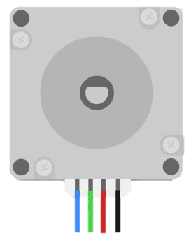
The NEMA23 stepper motor typically comes with 4, 6, or 8 wires, depending on the winding configuration. Below is the pinout for a common 4-wire bipolar stepper motor:
| Wire Color | Function | Description |
|---|---|---|
| Red | Coil A+ | Positive terminal of Coil A |
| Blue | Coil A- | Negative terminal of Coil A |
| Green | Coil B+ | Positive terminal of Coil B |
| Black | Coil B- | Negative terminal of Coil B |
For 6-wire or 8-wire motors, additional center-tap wires or parallel connections may be present. Refer to the motor's datasheet for detailed wiring diagrams.
Usage Instructions
How to Use the NEMA23 in a Circuit
- Power Supply: Ensure the power supply matches the motor's voltage and current ratings. Use a stepper motor driver to regulate current and protect the motor.
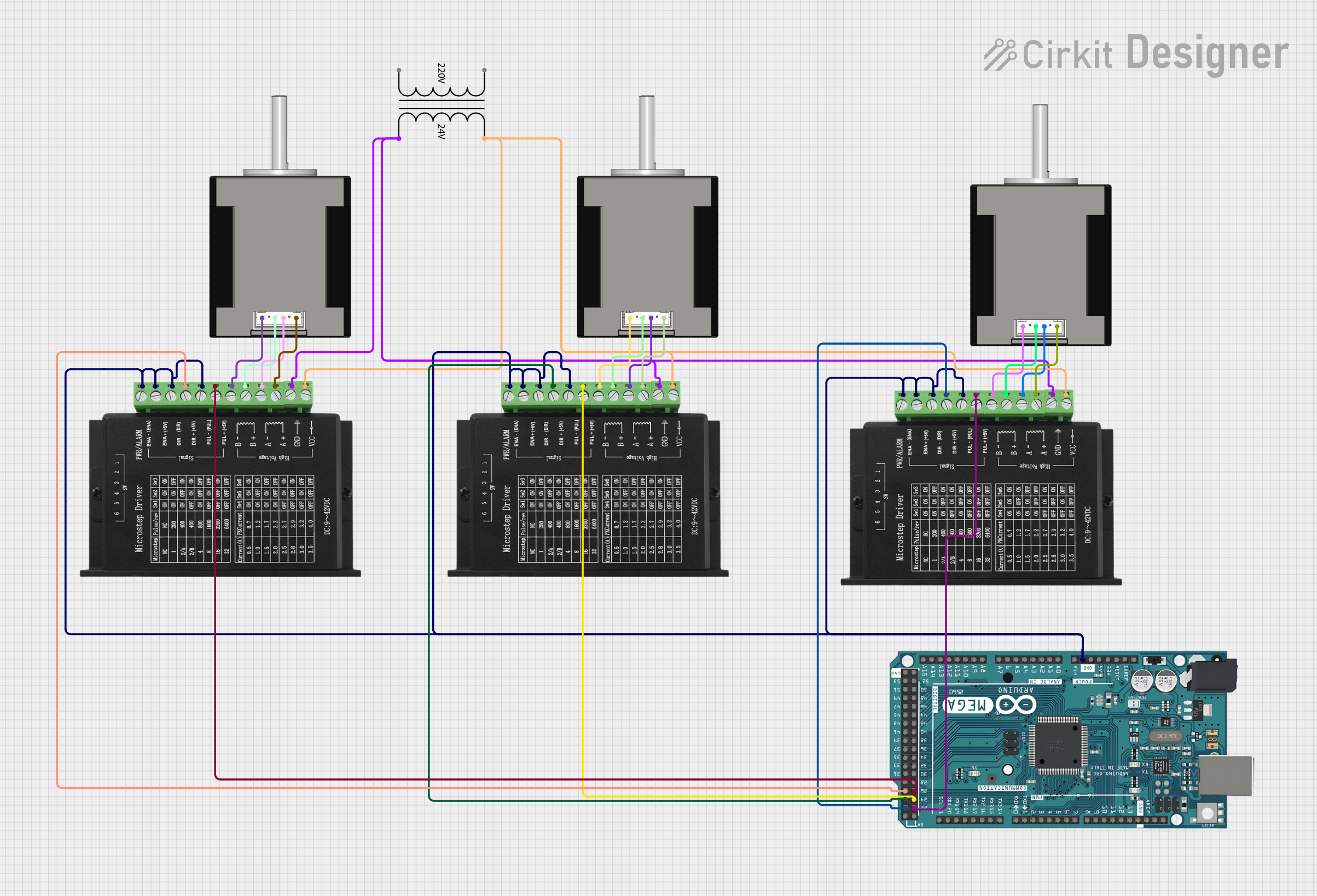
- Driver Connection: Connect the motor to a compatible stepper motor driver (e.g., A4988, DRV8825, or TB6600). Match the motor's coil wires to the driver's output terminals.
- Microcontroller Interface: Use a microcontroller (e.g., Arduino UNO) to send step and direction signals to the driver. The driver will translate these signals into precise motor movements.
- Wiring: Double-check all connections to avoid short circuits or incorrect wiring. Use a multimeter to verify coil pairs if needed.
Important Considerations and Best Practices
- Current Limiting: Set the current limit on the driver to match the motor's rated current. Exceeding this value can overheat and damage the motor.
- Cooling: Use a heatsink or fan for the driver if operating at high currents for extended periods.
- Step Resolution: Configure the driver for the desired microstepping mode (e.g., full step, half step, 1/8 step) to balance precision and torque.
- Backlash and Coupling: Minimize mechanical backlash by using proper couplings and ensuring secure mounting.
- Power Down: Avoid disconnecting the motor while powered, as this can damage the driver.
Example Code for Arduino UNO
Below is an example of controlling a NEMA23 stepper motor using an Arduino UNO and a TB6600 driver:
// Example: Controlling a NEMA23 stepper motor with Arduino UNO and TB6600 driver

// Define pin connections
const int stepPin = 3;  // Pin for step signal
const int dirPin = 4;   // Pin for direction signal

void setup() {
  pinMode(stepPin, OUTPUT);  // Set step pin as output
  pinMode(dirPin, OUTPUT);   // Set direction pin as output

  digitalWrite(dirPin, HIGH);  // Set initial direction (HIGH = CW, LOW = CCW)
}

void loop() {
  // Rotate motor 200 steps (1 full revolution for 1.8° step angle)
  for (int i = 0; i < 200; i++) {
    digitalWrite(stepPin, HIGH);  // Generate step pulse
    delayMicroseconds(500);       // Pulse width (adjust for speed)
    digitalWrite(stepPin, LOW);   // End step pulse
    delayMicroseconds(500);       // Delay between steps
  }

  delay(1000);  // Wait 1 second before changing direction

  // Reverse direction
  digitalWrite(dirPin, LOW);  // Change direction to CCW
  delay(1000);  // Wait 1 second before next loop
}
Notes:
- Adjust the
delayMicroseconds()values to control the motor speed. - Ensure the TB6600 driver's DIP switches are configured for the correct current and microstepping settings.
Troubleshooting and FAQs
Common Issues and Solutions
Motor Not Moving:
- Cause: Incorrect wiring or loose connections.
- Solution: Verify coil pairs with a multimeter and check all connections.
Motor Vibrates but Doesn't Rotate:
- Cause: Incorrect step sequence or insufficient current.
- Solution: Check the step and direction signals. Adjust the driver's current limit.
Overheating:
- Cause: Current limit set too high or poor ventilation.
- Solution: Reduce the current limit and ensure proper cooling.
Skipping Steps:
- Cause: Excessive load or incorrect microstepping settings.
- Solution: Reduce the load or increase the torque by lowering the microstepping resolution.
Driver Damage:
- Cause: Disconnecting the motor while powered.
- Solution: Always power down the system before making changes to wiring.
FAQs
Can I use a NEMA23 motor with a 12V power supply? Yes, but ensure the driver regulates the current to match the motor's rated current.
What is the advantage of microstepping? Microstepping increases motion smoothness and reduces noise but may slightly reduce torque.
How do I identify coil pairs on a 4-wire motor? Use a multimeter to measure resistance. Wires with the lowest resistance form a coil pair.
Can I run the motor without a driver? No, a stepper motor driver is essential for proper operation and current regulation.
By following this documentation, you can effectively integrate and operate a NEMA23 stepper motor in your projects.