
How to Use esp32 wroom 32e: Examples, Pinouts, and Specs
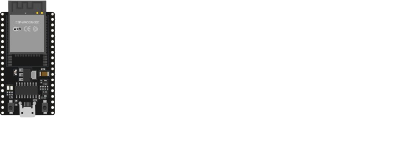
 Design with esp32 wroom 32e in Cirkit Designer
Introduction
The ESP32 WROOM 32E, manufactured by Espressif Systems (Part ID: DOS), is a high-performance microcontroller module designed for IoT and embedded applications. It features integrated Wi-Fi and Bluetooth capabilities, a dual-core processor, and a wide range of GPIO pins. This module is ideal for smart devices, home automation, industrial IoT, and other connected systems requiring robust wireless communication and processing power.
Explore Projects Built with esp32 wroom 32e
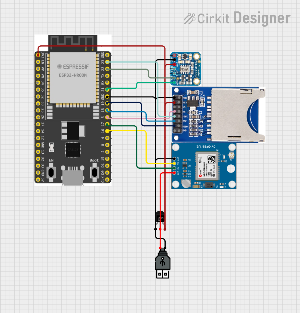 Open Project in Cirkit Designer
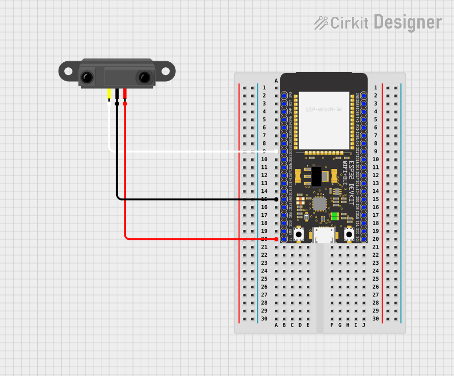 Open Project in Cirkit Designer
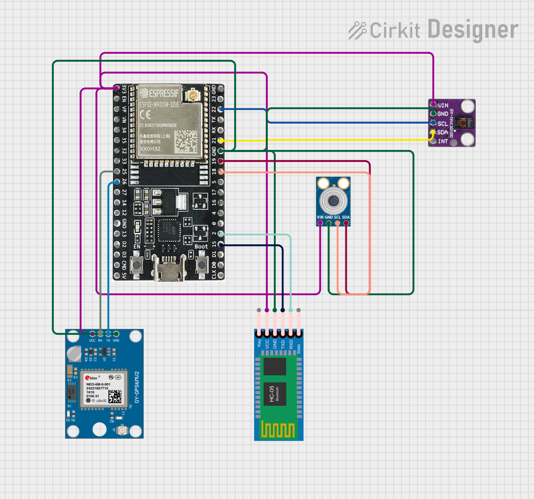 Open Project in Cirkit Designer
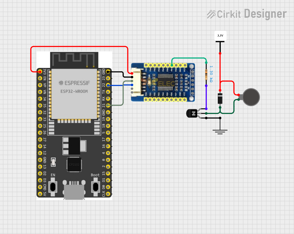 Open Project in Cirkit Designer
Explore Projects Built with esp32 wroom 32e
Open Project in Cirkit DesignerOpen Project in Cirkit DesignerOpen Project in Cirkit DesignerOpen Project in Cirkit DesignerCommon Applications
- IoT Devices: Smart home systems, environmental monitoring, and connected appliances.
- Wearable Technology: Fitness trackers and health monitoring devices.
- Industrial Automation: Remote monitoring and control systems.
- Prototyping: Rapid development of wireless communication projects.
- Smart Agriculture: Sensor networks for precision farming.
Technical Specifications
Key Technical Details
| Parameter | Value |
|---|---|
| Microcontroller | Xtensa® 32-bit LX6 dual-core processor |
| Clock Speed | Up to 240 MHz |
| Flash Memory | 4 MB (external SPI flash) |
| SRAM | 520 KB |
| Wireless Connectivity | Wi-Fi 802.11 b/g/n (2.4 GHz), Bluetooth v4.2 BR/EDR and BLE |
| Operating Voltage | 3.0V to 3.6V |
| GPIO Pins | 34 (multipurpose, including ADC, DAC, PWM, I2C, SPI, UART, etc.) |
| ADC Channels | 18 (12-bit resolution) |
| DAC Channels | 2 (8-bit resolution) |
| Communication Interfaces | UART, SPI, I2C, I2S, CAN, Ethernet MAC |
| Power Consumption (Active) | ~240 mA (Wi-Fi active) |
| Power Consumption (Deep Sleep) | ~10 µA |
| Operating Temperature Range | -40°C to +85°C |
| Dimensions | 18 mm x 25.5 mm x 3.1 mm |
Pin Configuration and Descriptions
The ESP32 WROOM 32E has 38 pins. Below is a summary of the key pins and their functions:
| Pin Number | Pin Name | Function |
|---|---|---|
| 1 | EN | Enable pin. Pull high to enable the module. |
| 2 | IO0 | GPIO0. Used for boot mode selection during programming. |
| 3 | IO2 | GPIO2. Can be used as a general-purpose input/output pin. |
| 4 | IO4 | GPIO4. Supports PWM, ADC, and other functions. |
| 5 | IO5 | GPIO5. Commonly used for SPI or general-purpose I/O. |
| 6 | GND | Ground. Connect to the ground of the power supply. |
| 7 | 3V3 | 3.3V power input. |
| 8 | IO12 | GPIO12. Supports ADC, PWM, and other functions. |
| 9 | IO13 | GPIO13. Commonly used for SPI or general-purpose I/O. |
| 10 | IO14 | GPIO14. Supports PWM, ADC, and other functions. |
| 11 | IO15 | GPIO15. Commonly used for SPI or general-purpose I/O. |
| 12 | IO16 | GPIO16. Can be used as a general-purpose input/output pin. |
| 13 | IO17 | GPIO17. Can be used as a general-purpose input/output pin. |
| 14 | IO18 | GPIO18. Commonly used for SPI or general-purpose I/O. |
| 15 | IO19 | GPIO19. Supports I2C, SPI, and other functions. |
| 16 | IO21 | GPIO21. Commonly used for I2C or general-purpose I/O. |
| 17 | IO22 | GPIO22. Commonly used for I2C or general-purpose I/O. |
| 18 | IO23 | GPIO23. Commonly used for SPI or general-purpose I/O. |
| 19 | IO25 | GPIO25. Supports DAC, ADC, and other functions. |
| 20 | IO26 | GPIO26. Supports DAC, ADC, and other functions. |
| 21 | IO27 | GPIO27. Supports ADC, PWM, and other functions. |
| 22 | IO32 | GPIO32. Supports ADC, PWM, and other functions. |
| 23 | IO33 | GPIO33. Supports ADC, PWM, and other functions. |
| 24 | IO34 | GPIO34. Input-only pin. Supports ADC. |
| 25 | IO35 | GPIO35. Input-only pin. Supports ADC. |
Usage Instructions
How to Use the ESP32 WROOM 32E in a Circuit
- Power Supply: Provide a stable 3.3V power supply to the module. Ensure the current rating of the power source is sufficient (at least 500 mA).
- Boot Mode: To program the ESP32, connect GPIO0 to GND and reset the module. After programming, disconnect GPIO0 from GND.
- Connections:
- Connect the EN pin to 3.3V through a pull-up resistor (10 kΩ recommended).
- Connect the GND pin to the ground of your circuit.
- Use the GPIO pins for interfacing with sensors, actuators, or other peripherals.
- Programming: Use the Arduino IDE or Espressif's ESP-IDF to write and upload code to the module.
Example: Blinking an LED with Arduino UNO
Below is an example of how to blink an LED connected to GPIO2 of the ESP32 WROOM 32E using the Arduino IDE:
// Define the GPIO pin where the LED is connected
#define LED_PIN 2

void setup() {
  pinMode(LED_PIN, OUTPUT);  // Set the LED pin as an output
}

void loop() {
  digitalWrite(LED_PIN, HIGH);  // Turn the LED on
  delay(1000);                  // Wait for 1 second
  digitalWrite(LED_PIN, LOW);   // Turn the LED off
  delay(1000);                  // Wait for 1 second
}
Important Considerations
- Voltage Levels: Ensure all connected peripherals operate at 3.3V logic levels to avoid damaging the module.
- Antenna Placement: Avoid placing metal objects near the onboard antenna to ensure optimal wireless performance.
- Heat Management: If the module operates in high-temperature environments, consider adding heat sinks or improving ventilation.
Troubleshooting and FAQs
Common Issues and Solutions
Module Not Responding:
- Ensure the EN pin is pulled high.
- Verify the power supply provides a stable 3.3V.
- Check all connections for loose wires or incorrect pin assignments.
Wi-Fi Connection Fails:
- Verify the SSID and password in your code.
- Ensure the router operates on the 2.4 GHz band (ESP32 does not support 5 GHz Wi-Fi).
Code Upload Fails:
- Ensure GPIO0 is connected to GND during programming.
- Check the USB-to-serial converter and its drivers on your computer.
Overheating:
- Verify the module is not drawing excessive current.
- Ensure proper ventilation around the module.
FAQs
Q: Can the ESP32 WROOM 32E operate on battery power?
A: Yes, the module can operate on battery power. Use a 3.3V regulator if the battery voltage exceeds 3.6V.
Q: How do I reset the module?
A: Pull the EN pin low momentarily to reset the module.
Q: Can I use the ESP32 WROOM 32E with a 5V logic device?
A: No, the ESP32 operates at 3.3V logic levels. Use a level shifter to interface with 5V devices.
This concludes the documentation for the ESP32 WROOM 32E. For further details, refer to the official datasheet provided by Espressif Systems.