Cirkit Designer Logo
Cirkit Designer
Your all-in-one circuit design IDE
Home / 
Component Documentation

How to Use BMS: Examples, Pinouts, and Specs

Image of BMS
Cirkit Designer LogoDesign with BMS in Cirkit Designer

Introduction

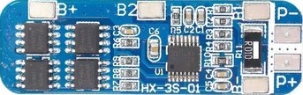
The 3S Battery Management System (BMS) is an electronic system designed to manage and protect a 3-cell series (3S) lithium-ion or lithium-polymer battery pack. It ensures the safe operation of rechargeable batteries by monitoring their state, controlling the charging and discharging process, and providing necessary protections. Common applications include portable electronics, electric vehicles, and energy storage systems.

Explore Projects Built with BMS

Use Cirkit Designer to design, explore, and prototype these projects online. Some projects support real-time simulation. Click "Open Project" to start designing instantly!
18650 Li-ion Battery Pack with BMS for 5V Power Supply
Image of battary: A project utilizing BMS in a practical application
This circuit consists of a battery management system (BMS) connected to a series of 18650 Li-ion batteries arranged in a 4S configuration to provide a regulated output voltage. The BMS ensures safe charging and discharging of the batteries, while a connector provides a 5V output for external devices.
Cirkit Designer LogoOpen Project in Cirkit Designer
Li-ion Battery Management and Monitoring System with Voltage Regulation and Relay Control
Image of Portable Inverter: A project utilizing BMS in a practical application
This is a power management system with a series-connected battery pack managed by a BMS, providing regulated power to a microcontroller and a fan. It includes voltage and current sensing, a relay for load control, and a step-up converter for an external power source.
Cirkit Designer LogoOpen Project in Cirkit Designer
18650 Li-ion Battery-Powered BMS with Boost Converter and 5V Adapter
Image of dog: A project utilizing BMS in a practical application
This circuit consists of three 18650 Li-ion batteries connected in parallel to a Battery Management System (BMS), which ensures safe charging and discharging of the batteries. The BMS output is connected to a 5V adapter and an XL6009E1 Boost Converter, indicating that the circuit is designed to provide a regulated power supply, likely stepping up the voltage to a required level for downstream electronics.
Cirkit Designer LogoOpen Project in Cirkit Designer
Battery-Powered Adjustable Voltage Regulator with Li-ion 18650 Batteries and BMS
Image of mini ups: A project utilizing BMS in a practical application
This circuit is a power management system that uses four Li-ion 18650 batteries connected to a 2S 30A BMS for battery management and protection. The system includes step-up and step-down voltage regulators to provide adjustable output voltages, controlled by a rocker switch, and multiple DC jacks for power input and output.
Cirkit Designer LogoOpen Project in Cirkit Designer

Explore Projects Built with BMS

Use Cirkit Designer to design, explore, and prototype these projects online. Some projects support real-time simulation. Click "Open Project" to start designing instantly!
Image of battary: A project utilizing BMS in a practical application
18650 Li-ion Battery Pack with BMS for 5V Power Supply
This circuit consists of a battery management system (BMS) connected to a series of 18650 Li-ion batteries arranged in a 4S configuration to provide a regulated output voltage. The BMS ensures safe charging and discharging of the batteries, while a connector provides a 5V output for external devices.
Cirkit Designer LogoOpen Project in Cirkit Designer
Image of Portable Inverter: A project utilizing BMS in a practical application
Li-ion Battery Management and Monitoring System with Voltage Regulation and Relay Control
This is a power management system with a series-connected battery pack managed by a BMS, providing regulated power to a microcontroller and a fan. It includes voltage and current sensing, a relay for load control, and a step-up converter for an external power source.
Cirkit Designer LogoOpen Project in Cirkit Designer
Image of dog: A project utilizing BMS in a practical application
18650 Li-ion Battery-Powered BMS with Boost Converter and 5V Adapter
This circuit consists of three 18650 Li-ion batteries connected in parallel to a Battery Management System (BMS), which ensures safe charging and discharging of the batteries. The BMS output is connected to a 5V adapter and an XL6009E1 Boost Converter, indicating that the circuit is designed to provide a regulated power supply, likely stepping up the voltage to a required level for downstream electronics.
Cirkit Designer LogoOpen Project in Cirkit Designer
Image of mini ups: A project utilizing BMS in a practical application
Battery-Powered Adjustable Voltage Regulator with Li-ion 18650 Batteries and BMS
This circuit is a power management system that uses four Li-ion 18650 batteries connected to a 2S 30A BMS for battery management and protection. The system includes step-up and step-down voltage regulators to provide adjustable output voltages, controlled by a rocker switch, and multiple DC jacks for power input and output.
Cirkit Designer LogoOpen Project in Cirkit Designer

Technical Specifications

Key Technical Details

  • Voltage Range: Typically 10.8V to 12.6V (for 3S Li-ion or Li-Po batteries)
  • Max Continuous Discharge Current: Specified by manufacturer (e.g., 20A)
  • Max Continuous Charge Current: Specified by manufacturer (e.g., 5A)
  • Balancing Voltage: Typically around 4.2V per cell
  • Balancing Current: Specified by manufacturer (e.g., 60mA)
  • Overcharge Protection Threshold: Typically around 4.25V per cell
  • Over-discharge Protection Threshold: Typically around 2.7V per cell
  • Short Circuit Protection: Yes
  • Operating Temperature Range: Specified by manufacturer (e.g., -20°C to 70°C)

Pin Configuration and Descriptions

Pin Number Description Notes
P+ Positive battery output Connect to battery positive
P- Negative battery output Connect to battery negative
B+ Positive battery connection Connect to positive of cell 3
B2 Cell 2 positive connection Connect to positive of cell 2
B1 Cell 1 positive connection Connect to positive of cell 1
B- Negative battery connection Connect to negative of cell 1
C+ Charge positive Connect to charger positive
C- Charge negative Connect to charger negative

Usage Instructions

How to Use the Component in a Circuit

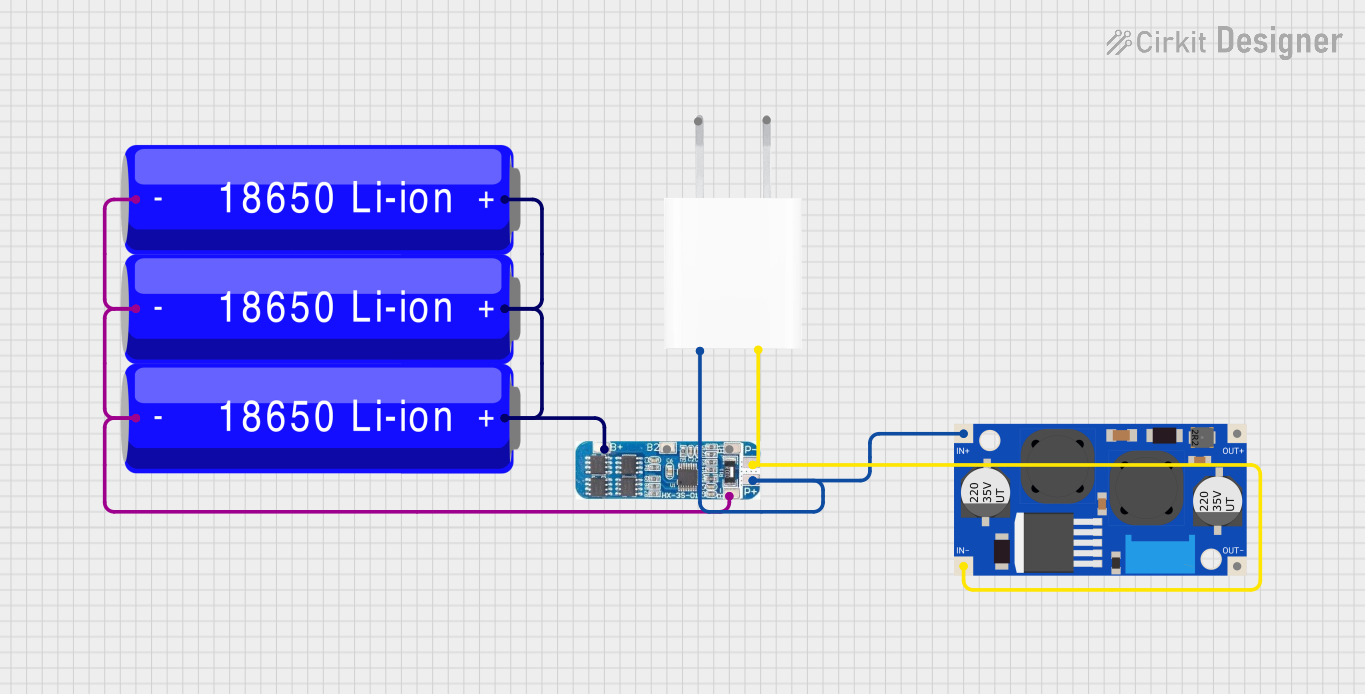
  1. Battery Connection: Connect the BMS to the battery pack by soldering the B+, B1, B2, and B- to the corresponding terminals of the battery cells in series.
  2. Charging Connection: Connect the C+ and C- to the charger's positive and negative terminals, respectively.
  3. Load Connection: Connect the P+ and P- to the load's positive and negative inputs, respectively.
  4. Insulation: Ensure all connections are well insulated to prevent short circuits.

Important Considerations and Best Practices

  • Battery Compatibility: Ensure the BMS is compatible with the specific chemistry and configuration of your battery pack.
  • Current Ratings: Do not exceed the BMS's maximum charge and discharge current ratings.
  • Temperature: Operate within the recommended temperature range to prevent damage.
  • Mounting: Secure the BMS to prevent movement and potential shorts.
  • Inspection: Regularly inspect connections for signs of wear or corrosion.

Troubleshooting and FAQs

Common Issues

  • BMS not balancing cells: Ensure all connections are secure and the cells are within the operational voltage range.
  • BMS cuts off power prematurely: Check if the cells are below the over-discharge threshold or if there is a short circuit.
  • Charging doesn't start: Verify that the charger is functioning and the charging voltage is within the BMS specifications.

Solutions and Tips for Troubleshooting

  • Check Connections: Loose or poor connections can cause various issues. Ensure all solder joints and connections are secure.
  • Measure Cell Voltages: Use a multimeter to check the voltage of each cell. They should be within the BMS operating range.
  • Inspect for Damage: Look for any signs of physical damage to the BMS or battery cells.

FAQs

Q: Can I use the 3S BMS with a 2S or 4S battery pack? A: No, the 3S BMS is specifically designed for 3-cell series configurations.

Q: What should I do if one cell is not charging properly? A: Check the cell's voltage and connections. If the cell is damaged, it may need to be replaced.

Q: How do I know if the BMS is working correctly? A: The BMS should maintain balance between the cells and protect against overcharging and over-discharging. Use a multimeter to monitor cell voltages during operation.

Note: This documentation is for informational purposes only. Always consult the manufacturer's datasheet for the most accurate and detailed information about the 3S BMS.