How to Use MKE-M10 I2C Motor Control Module: Examples, Pinouts, and Specs
Introduction
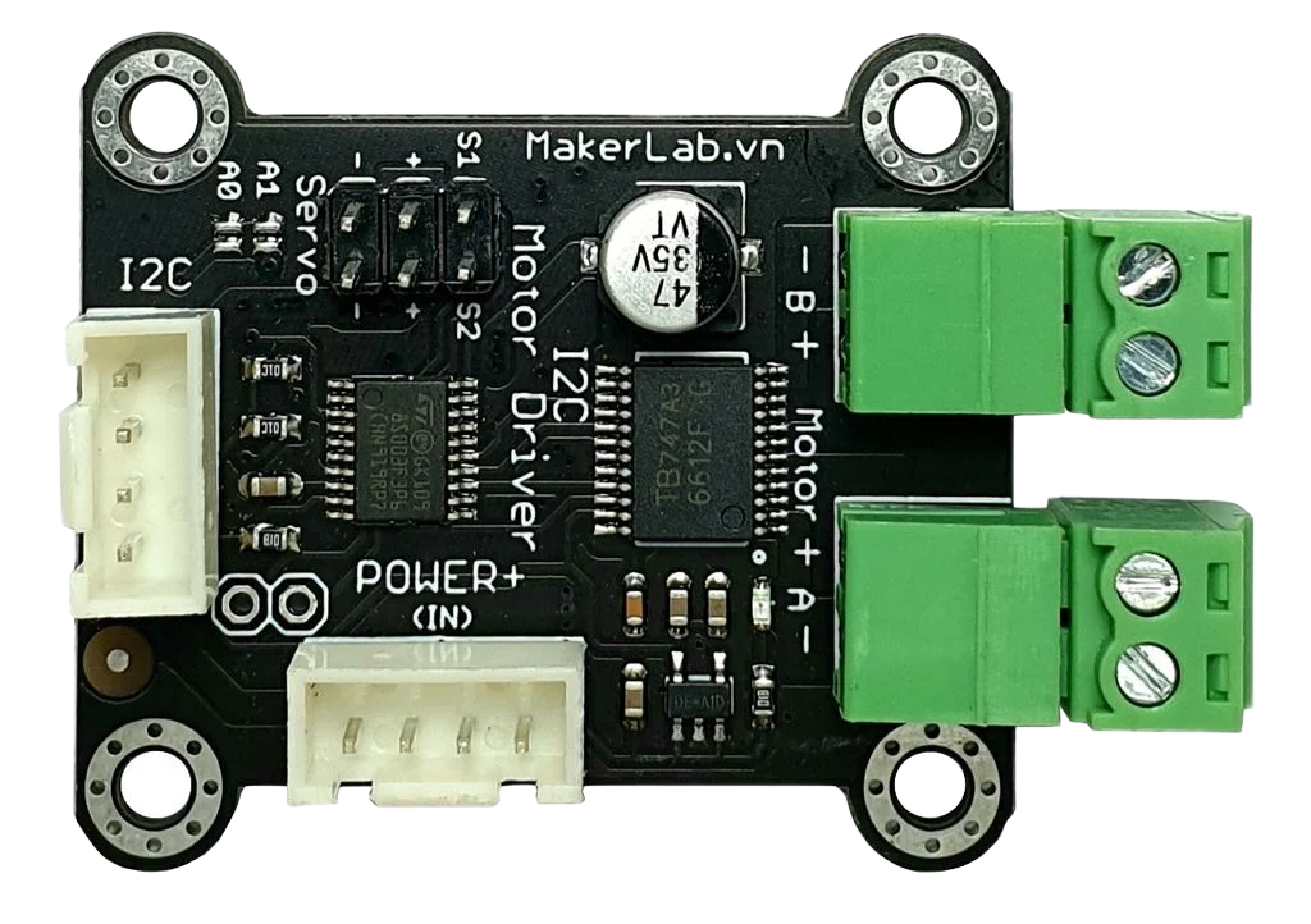
The MKE-M10 I2C Motor Control Module is a versatile and compact motor driver designed for controlling motors through the I2C communication protocol. This module simplifies the process of driving both DC and stepper motors, making it an ideal choice for robotics, automation projects, and other applications where precise motor control is required.
Explore Projects Built with MKE-M10 I2C Motor Control Module

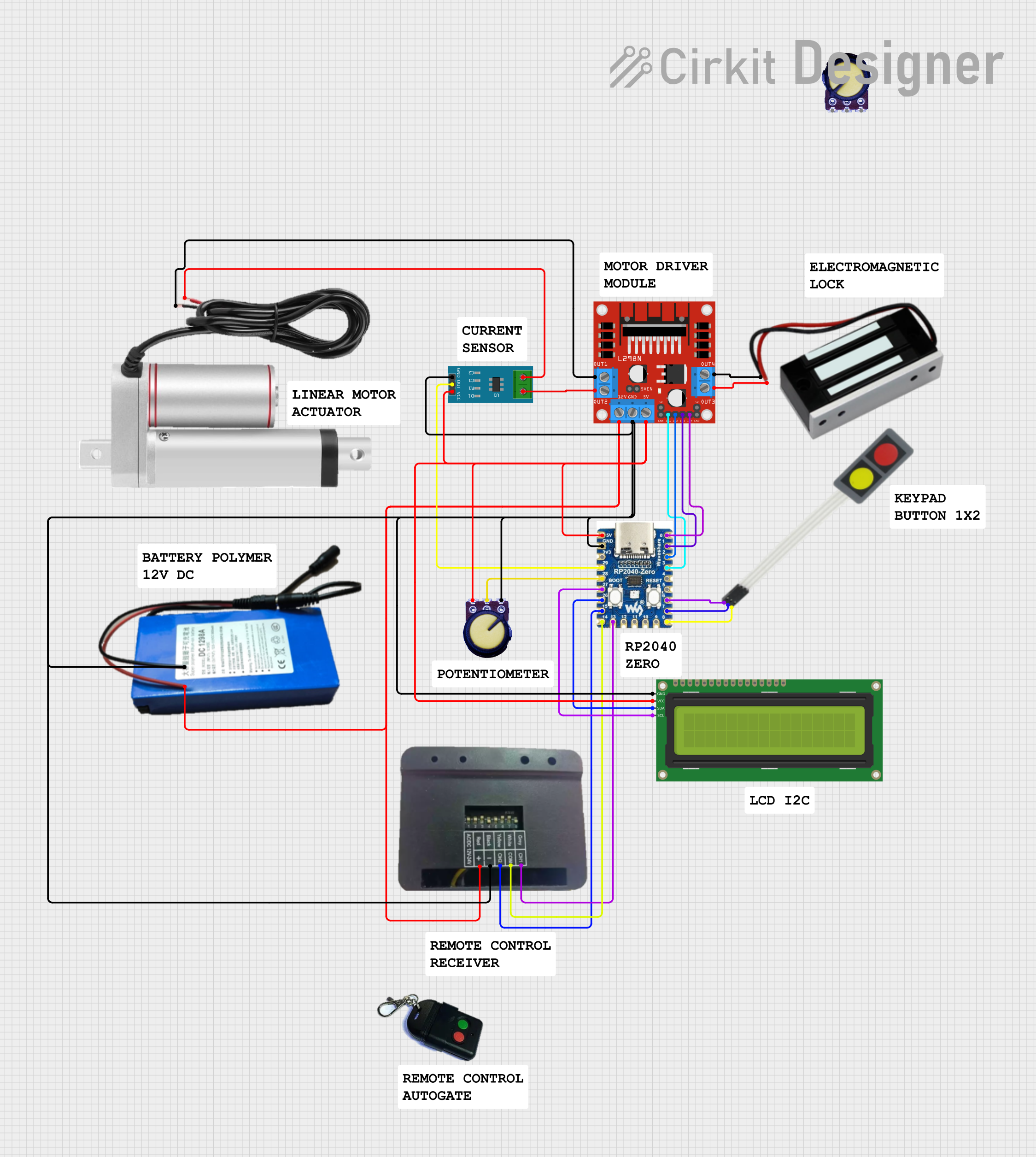
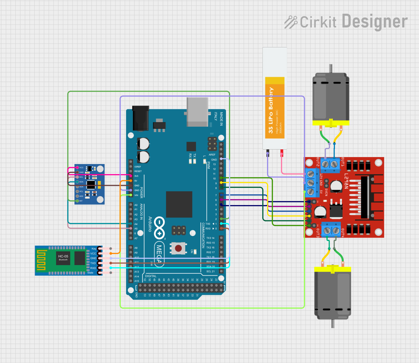
Explore Projects Built with MKE-M10 I2C Motor Control Module
Common Applications and Use Cases
- Robotics
- Automated equipment
- Hobbyist projects
- Educational platforms
- Prototyping and development
Technical Specifications
Key Technical Details
- Operating Voltage: 2.5V to 5.5V
- Output Current: Up to 1.2A per channel
- Communication: I2C interface
- I2C Address: Configurable
- Motor Control: Supports both DC and stepper motors
Pin Configuration and Descriptions
| Pin Number | Pin Name | Description |
|---|---|---|
| 1 | VCC | Power supply input (2.5V to 5.5V) |
| 2 | GND | Ground |
| 3 | SDA | I2C Data Line |
| 4 | SCL | I2C Clock Line |
| 5 | A1 | Motor output A1 |
| 6 | A2 | Motor output A2 |
| 7 | B1 | Motor output B1 (for stepper motor control) |
| 8 | B2 | Motor output B2 (for stepper motor control) |
| 9 | ADDR | I2C Address selection pin |
Usage Instructions
How to Use the Component in a Circuit
- Power Supply: Connect the VCC pin to a suitable power supply (2.5V to 5.5V) and the GND pin to the ground.
- I2C Connection: Connect the SDA and SCL pins to the corresponding I2C data and clock lines on your microcontroller.
- Motor Connection: Connect your motor to the output pins (A1 and A2 for DC motors, A1, A2, B1, and B2 for stepper motors).
- Address Selection: Set the ADDR pin to the desired logic level to configure the I2C address if multiple modules are used.
Important Considerations and Best Practices
- Ensure that the power supply voltage and motor current do not exceed the module's specifications.
- Use pull-up resistors on the I2C lines if they are not already present on the microcontroller board.
- Avoid running motors at full current for extended periods to prevent overheating.
- Implement proper decoupling using capacitors close to the module's power supply pins.
Example Code for Arduino UNO
#include <Wire.h>

// Define the I2C address of the MKE-M10 module
#define MOTOR_I2C_ADDRESS 0x10

void setup() {
  Wire.begin(); // Join the I2C bus as a master
  // Initialize the motor control module
  initMotorControl();
}

void loop() {
  // Example: Drive the motor forward
  driveMotorForward();
  delay(1000);

  // Example: Stop the motor
  stopMotor();
  delay(1000);

  // Example: Drive the motor in reverse
  driveMotorReverse();
  delay(1000);

  // Example: Stop the motor
  stopMotor();
  delay(1000);
}

void initMotorControl() {
  // Code to initialize the motor control module
}

void driveMotorForward() {
  // Code to drive the motor forward
  Wire.beginTransmission(MOTOR_I2C_ADDRESS);
  Wire.write(0x01); // Command to drive forward
  Wire.endTransmission();
}

void stopMotor() {
  // Code to stop the motor
  Wire.beginTransmission(MOTOR_I2C_ADDRESS);
  Wire.write(0x00); // Command to stop
  Wire.endTransmission();
}

void driveMotorReverse() {
  // Code to drive the motor in reverse
  Wire.beginTransmission(MOTOR_I2C_ADDRESS);
  Wire.write(0x02); // Command to reverse
  Wire.endTransmission();
}
Troubleshooting and FAQs
Common Issues Users Might Face
- Motor not responding: Check the power supply and connections. Ensure the I2C address is correctly set and matches the code.
- Weak motor performance: Verify that the motor's power requirements do not exceed the module's limits. Check for any signs of overheating.
- I2C communication errors: Ensure pull-up resistors are in place and that there are no conflicts with other devices on the I2C bus.
Solutions and Tips for Troubleshooting
- Double-check wiring and solder joints for any loose connections or shorts.
- Use a multimeter to verify the voltage at the VCC and GND pins.
- Use an oscilloscope or logic analyzer to check the I2C signals for integrity.
- Isolate the motor control module from other I2C devices to determine if there is a conflict.
FAQs:
Q: Can the MKE-M10 module control two motors simultaneously? A: Yes, it can control two DC motors or one stepper motor.
Q: What is the maximum frequency for the I2C clock? A: The maximum I2C clock frequency for the MKE-M10 module is typically 400kHz (Fast-mode I2C).
Q: How do I change the I2C address of the module? A: The I2C address can be changed by adjusting the logic level of the ADDR pin. Refer to the module's datasheet for the address mapping table.