How to Use Vietduino Wifi BLE ESP32: Examples, Pinouts, and Specs
Introduction
The Vietduino Wifi BLE ESP32 is a versatile microcontroller board designed for a wide range of applications, particularly in the Internet of Things (IoT) domain. Based on the Espressif ESP32 system-on-chip (SoC), it integrates Wi-Fi and Bluetooth Low Energy (BLE) for wireless communication, making it an ideal choice for projects that require remote connectivity and data exchange.
Explore Projects Built with Vietduino Wifi BLE ESP32
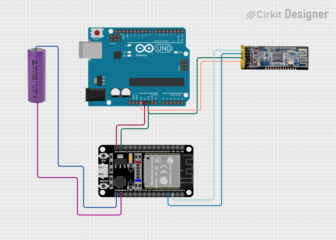
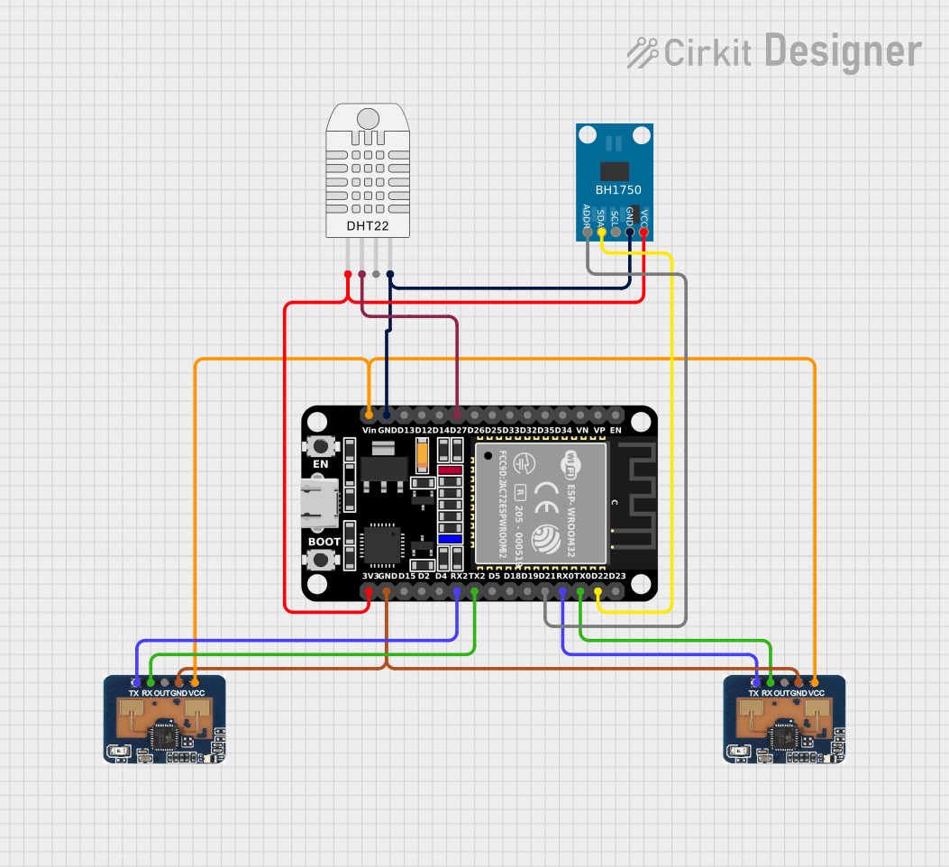


Explore Projects Built with Vietduino Wifi BLE ESP32
Common Applications and Use Cases
- Smart home devices
- Wireless sensor networks
- IoT gateways
- Wearable electronics
- Remote monitoring and control systems
Technical Specifications
Key Technical Details
- Microcontroller: ESP32-D0WDQ6
- Operating Voltage: 3.3V
- Input Voltage (recommended): 5V via micro USB
- Digital I/O Pins: 22
- Analog Input Pins: 6 (ADC 12-bit)
- Analog Output Pins: 2 (DAC 8-bit)
- Flash Memory: 4 MB
- SRAM: 520 KB
- Clock Speed: 240 MHz
- Wi-Fi: 802.11 b/g/n
- Bluetooth: v4.2 BR/EDR and BLE standards
Pin Configuration and Descriptions
| Pin Number | Function | Description |
|---|---|---|
| 1 | 3V3 | 3.3V power supply |
| 2 | GND | Ground |
| 3 | EN | Reset pin (active low) |
| 4-9 | GPIO 1-6 | General-purpose input/output pins |
| 10-15 | GPIO 12-17 | General-purpose input/output pins |
| 16 | VIN | Input voltage for battery or external power |
| 17 | TX0 | UART0 transmit |
| 18 | RX0 | UART0 receive |
| 19 | GPIO 21 | General-purpose input/output pin |
| 20 | GPIO 22 | General-purpose input/output pin |
| 21 | GPIO 23 | General-purpose input/output pin |
| 22 | GPIO 25 | DAC1 |
| 23 | GPIO 26 | DAC2 |
| 24 | GPIO 27 | General-purpose input/output pin |
| 25 | GPIO 32 | General-purpose input/output pin |
| 26 | GPIO 33 | General-purpose input/output pin |
| 27 | GPIO 34 (input only) | Analog input pin |
| 28 | GPIO 35 (input only) | Analog input pin |
| 29 | GPIO 36 (input only) | Analog input pin |
| 30 | GPIO 39 (input only) | Analog input pin |
Usage Instructions
How to Use the Component in a Circuit
- Powering the Board: Connect a 5V power supply to the VIN pin or use the micro USB port.
- Connecting I/O: Utilize the GPIO pins for interfacing with sensors, actuators, and other peripherals.
- Programming: Use the Arduino IDE or other development environments to upload code to the board.
Important Considerations and Best Practices
- Ensure that the input voltage does not exceed the recommended 5V to avoid damaging the board.
- When using Wi-Fi or BLE, consider the power consumption and plan for adequate power supply.
- Use proper decoupling capacitors close to the power pins to minimize noise.
- Avoid drawing more than 12 mA from any GPIO pin.
- For analog readings, ensure that the input voltage range is between 0V and 3.3V.
Troubleshooting and FAQs
Common Issues Users Might Face
- Board not responding: Ensure that the board is properly powered and the USB drivers are installed.
- Wi-Fi/BLE not functioning: Check the antenna connections and ensure that the correct libraries are included in the code.
Solutions and Tips for Troubleshooting
- Reset the board: Press the EN button to reset the board if it becomes unresponsive.
- Update firmware: Make sure the ESP32 board definitions are up to date in the Arduino IDE.
- Check connections: Verify that all connections are secure and correct.
FAQs
Q: Can I use the Vietduino Wifi BLE ESP32 with the Arduino IDE? A: Yes, the board is compatible with the Arduino IDE. You will need to install the ESP32 board package.
Q: What is the maximum current that can be drawn from the 3.3V pin? A: The maximum current draw from the 3.3V pin should not exceed 500 mA.
Q: How do I enable Bluetooth on the Vietduino Wifi BLE ESP32? A: Bluetooth can be enabled by including the appropriate BLE libraries in your Arduino sketch and initializing the BLE mode in your code.
Example Code for Arduino UNO
#include <WiFi.h>

// Replace with your network credentials
const char* ssid = "your_SSID";
const char* password = "your_PASSWORD";

void setup() {
  Serial.begin(115200);

  // Connect to Wi-Fi
  WiFi.begin(ssid, password);
  while (WiFi.status() != WL_CONNECTED) {
    delay(500);
    Serial.println("Connecting to WiFi...");
  }
  Serial.println("Connected to WiFi");
}

void loop() {
  // Put your main code here, to run repeatedly:
}
Note: This example demonstrates how to connect the Vietduino Wifi BLE ESP32 to a Wi-Fi network. Make sure to replace your_SSID and your_PASSWORD with your actual Wi-Fi network credentials.