How to Use Silent Step Click: Examples, Pinouts, and Specs
Introduction
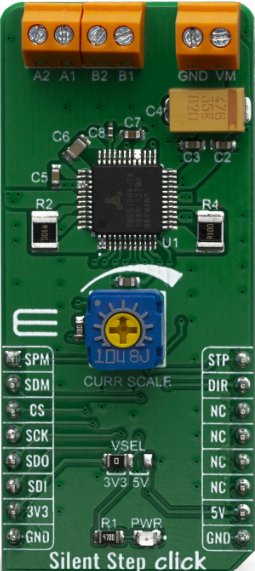
The Silent Step Click (Manufacturer Part ID: MIKROE-3714) is a specialized electronic component designed by Mikroelectronica to provide silent and precise stepper motor control. It is based on the TMC2130 stepper motor driver IC, which offers advanced features such as StealthChop™ for ultra-quiet operation and SpreadCycle™ for high-performance motion control. This makes it ideal for applications where noise reduction is critical, such as audio equipment, medical devices, 3D printers, and other sensitive electronic systems.
The Silent Step Click is designed to work seamlessly with MikroElektronika's mikroBUS™ socket, enabling easy integration into development boards and projects.
Explore Projects Built with Silent Step Click

Explore Projects Built with Silent Step Click
Technical Specifications
Key Technical Details
- Driver IC: TMC2130 by Trinamic
- Input Voltage: 3.3V or 5V (via mikroBUS™)
- Motor Voltage Range: 4.75V to 46V
- Maximum Motor Current: Up to 1.2A RMS (2.5A peak)
- Microstepping Resolution: Up to 1/256 steps
- Communication Interface: SPI
- Features:
- StealthChop™ for silent operation
- SpreadCycle™ for smooth motion
- StallGuard™ for sensorless load detection
- CoolStep™ for energy-efficient operation
Pin Configuration and Descriptions
The Silent Step Click uses the mikroBUS™ standard pinout. Below is the pin configuration:
| Pin | Name | Description |
|---|---|---|
| 1 | AN | Not connected (reserved for future use) |
| 2 | RST | Reset pin for the driver |
| 3 | CS | Chip Select for SPI communication |
| 4 | SCK | SPI Clock |
| 5 | MISO | Master In Slave Out (data from Silent Step Click to the microcontroller) |
| 6 | MOSI | Master Out Slave In (data from the microcontroller to Silent Step Click) |
| 7 | PWM | Pulse Width Modulation input for controlling motor speed |
| 8 | INT | Interrupt pin for signaling events such as stall detection |
| 9 | GND | Ground connection |
| 10 | 3.3V | Power supply input (3.3V) |
| 11 | 5V | Power supply input (5V) |
| 12 | NC | Not connected |
Usage Instructions
How to Use the Silent Step Click in a Circuit
- Power Supply: Connect the Silent Step Click to a 3.3V or 5V power source via the mikroBUS™ socket. Ensure the motor voltage (VM) is within the range of 4.75V to 46V.
- Motor Connection: Connect the stepper motor to the motor output terminals on the Silent Step Click. Ensure the motor's current rating does not exceed the driver's maximum current capacity.
- SPI Communication: Use the SPI pins (CS, SCK, MISO, MOSI) to interface with a microcontroller. Configure the SPI settings in your microcontroller to match the Silent Step Click's requirements.
- Control Signals: Use the PWM pin to control motor speed and the INT pin to monitor events such as stall detection.
- Microstepping: Configure the microstepping resolution via SPI commands for precise motor control.
Important Considerations and Best Practices
- Cooling: Ensure adequate cooling for the driver IC, especially when operating at high currents.
- Power Supply: Use a stable and noise-free power supply to avoid erratic motor behavior.
- Motor Compatibility: Verify that the stepper motor's voltage and current ratings are compatible with the Silent Step Click.
- SPI Configuration: Set the SPI clock speed and mode correctly to ensure reliable communication.
- StallGuard™ and CoolStep™: Enable these features via SPI commands for advanced motor control and energy efficiency.
Example Code for Arduino UNO
Below is an example of how to interface the Silent Step Click with an Arduino UNO using SPI:
#include <SPI.h>

// Define SPI pins for Arduino UNO
const int CS_PIN = 10; // Chip Select pin
const int RST_PIN = 9; // Reset pin

void setup() {
  // Initialize Serial Monitor
  Serial.begin(9600);

  // Configure SPI settings
  SPI.begin();
  pinMode(CS_PIN, OUTPUT);
  pinMode(RST_PIN, OUTPUT);

  // Reset the Silent Step Click
  digitalWrite(RST_PIN, LOW);
  delay(10);
  digitalWrite(RST_PIN, HIGH);
  delay(10);

  // Initialize Silent Step Click
  digitalWrite(CS_PIN, LOW);
  SPI.transfer(0x80); // Example command to configure the driver
  SPI.transfer(0x00); // Example data
  digitalWrite(CS_PIN, HIGH);

  Serial.println("Silent Step Click initialized.");
}

void loop() {
  // Example: Send a command to move the motor
  digitalWrite(CS_PIN, LOW);
  SPI.transfer(0xA0); // Example command to move the motor
  SPI.transfer(0x01); // Example data
  digitalWrite(CS_PIN, HIGH);

  delay(1000); // Wait for 1 second
}
Note: Replace the example SPI commands (0x80, 0xA0, etc.) with actual commands based on the TMC2130 datasheet and your application requirements.
Troubleshooting and FAQs
Common Issues and Solutions
Motor Not Moving:
- Ensure the motor is properly connected to the Silent Step Click.
- Verify that the motor voltage and current ratings are within the driver's specifications.
- Check the SPI communication settings and ensure the correct commands are being sent.
Overheating:
- Ensure adequate cooling for the driver IC.
- Reduce the motor current via SPI commands if overheating persists.
Noisy Operation:
- Enable StealthChop™ mode via SPI commands for silent operation.
- Verify that the motor is compatible with the Silent Step Click.
Stall Detection Not Working:
- Ensure StallGuard™ is enabled via SPI commands.
- Verify that the motor is under load for accurate stall detection.
FAQs
Can I use the Silent Step Click with a 12V stepper motor? Yes, as long as the motor's voltage and current ratings are within the driver's specifications.
What is the maximum microstepping resolution? The Silent Step Click supports up to 1/256 microstepping resolution.
Is the Silent Step Click compatible with 5V logic? Yes, it supports both 3.3V and 5V logic levels via the mikroBUS™ socket.
How do I enable StealthChop™ mode? StealthChop™ can be enabled via SPI commands. Refer to the TMC2130 datasheet for detailed instructions.
By following this documentation, users can effectively integrate the Silent Step Click into their projects and achieve precise, silent stepper motor control.