Cirkit Designer
Your all-in-one circuit design IDE
Home /
Component Documentation
How to Use 4-digit FND: Examples, Pinouts, and Specs
Introduction
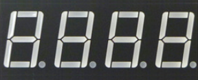
The 4-digit FND (Four-Digit Seven-Segment Display) is a versatile electronic component designed to display numerical information. Manufactured by Custom with the part ID 4-digit FND, this display is commonly used in applications such as digital clocks, counters, and various other digital displays. Its ability to show four digits makes it ideal for scenarios where multiple numerical values need to be displayed simultaneously.
Explore Projects Built with 4-digit FND
VINT Hub-Controlled Multi-Stepper Motor System

This circuit consists of a VINT Hub Phidget connected to four 4A Stepper Phidgets, which in turn are connected to four NEMA23 stepper motors. The VINT Hub Phidget interfaces with the stepper controllers, likely for the purpose of controlling the stepper motors. A power supply is connected to all the stepper controllers to provide the necessary voltage, and a Square FSR (Force Sensitive Resistor) with a resistor is connected to the VINT Hub, possibly for sensing force or pressure.
Arduino-Based Fingerprint Access Control System with LCD Display
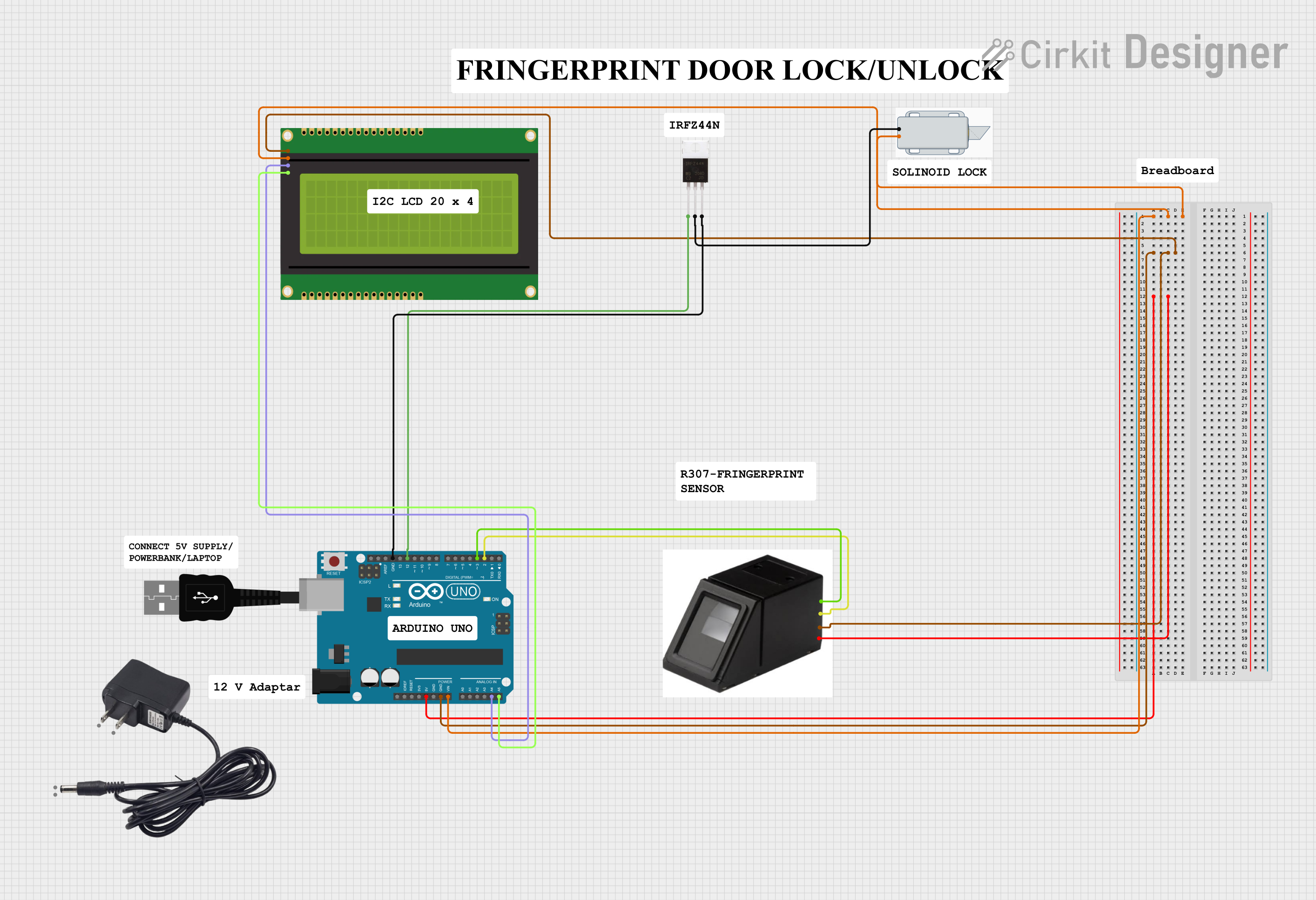
This circuit is a fingerprint-based access control system. It uses an Arduino UNO to interface with a fingerprint sensor and a 20x4 I2C LCD panel for user interaction, and controls a 12V solenoid lock via an IRFZ44N MOSFET. The system allows users to enroll and verify fingerprints, displaying status messages on the LCD and actuating the solenoid lock upon successful verification.
Arduino UNO-Based Smart Door Lock with Fingerprint, Keypad, and LCD Display
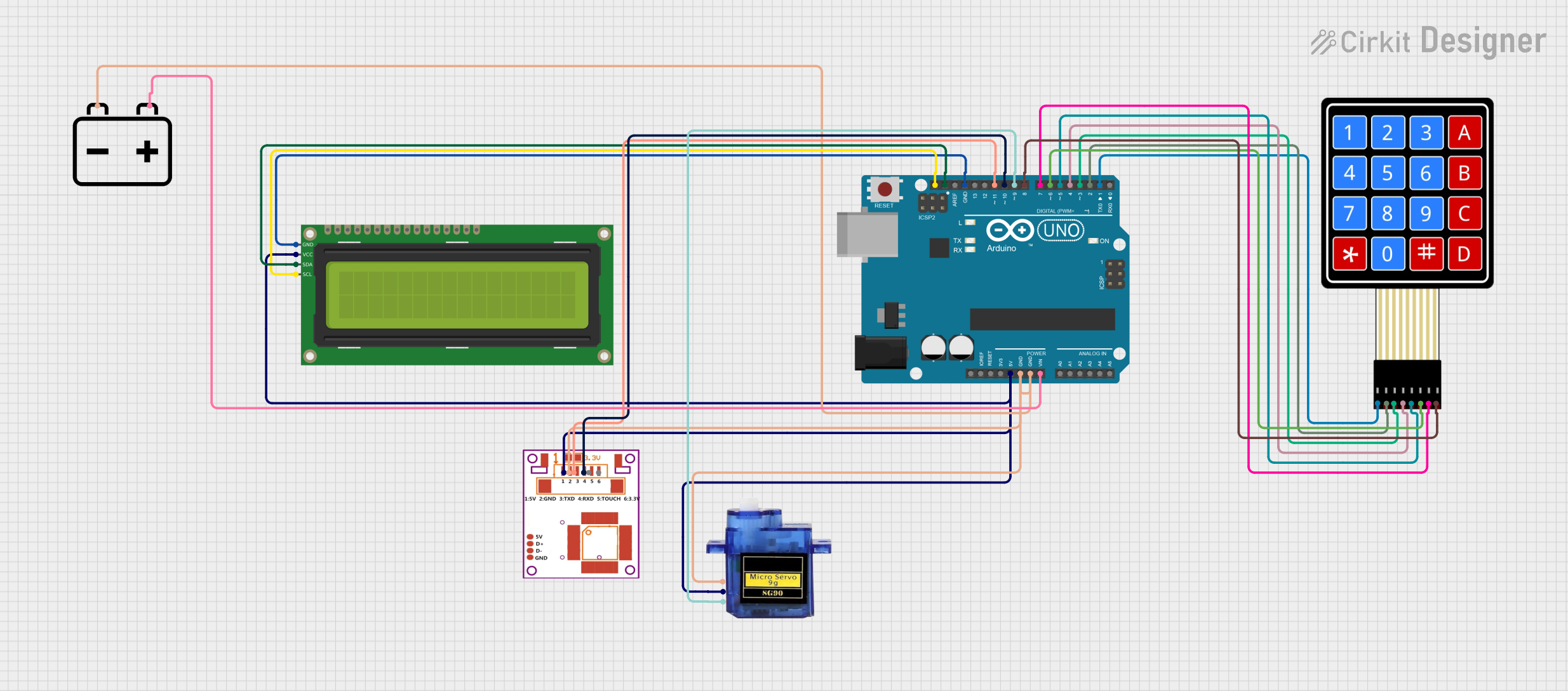
This circuit is a multi-factor authentication door lock system that uses an Arduino UNO to control a fingerprint sensor, a 4x4 membrane keypad, a 16x2 I2C LCD, and a micro servo. The system verifies user identity through RFID tags, a keypad password, and a fingerprint scan, displaying status messages on the LCD and controlling the servo to lock or unlock the door.
Arduino UNO-Based Smart Item Booking System with Bluetooth and LCD Display
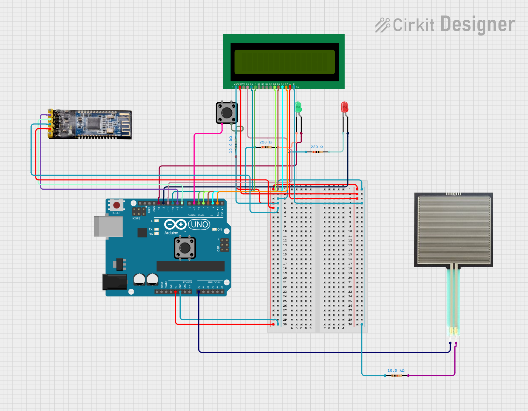
This circuit uses an Arduino UNO to monitor a force-sensitive resistor (FSR) and control LEDs and an LCD display to indicate the availability of an item. It also includes a Bluetooth module for sending notifications and a button to simulate booking the item, with the status displayed on the LCD.
Explore Projects Built with 4-digit FND
VINT Hub-Controlled Multi-Stepper Motor System
This circuit consists of a VINT Hub Phidget connected to four 4A Stepper Phidgets, which in turn are connected to four NEMA23 stepper motors. The VINT Hub Phidget interfaces with the stepper controllers, likely for the purpose of controlling the stepper motors. A power supply is connected to all the stepper controllers to provide the necessary voltage, and a Square FSR (Force Sensitive Resistor) with a resistor is connected to the VINT Hub, possibly for sensing force or pressure.
Arduino-Based Fingerprint Access Control System with LCD Display
This circuit is a fingerprint-based access control system. It uses an Arduino UNO to interface with a fingerprint sensor and a 20x4 I2C LCD panel for user interaction, and controls a 12V solenoid lock via an IRFZ44N MOSFET. The system allows users to enroll and verify fingerprints, displaying status messages on the LCD and actuating the solenoid lock upon successful verification.
Arduino UNO-Based Smart Door Lock with Fingerprint, Keypad, and LCD Display
This circuit is a multi-factor authentication door lock system that uses an Arduino UNO to control a fingerprint sensor, a 4x4 membrane keypad, a 16x2 I2C LCD, and a micro servo. The system verifies user identity through RFID tags, a keypad password, and a fingerprint scan, displaying status messages on the LCD and controlling the servo to lock or unlock the door.
Arduino UNO-Based Smart Item Booking System with Bluetooth and LCD Display
This circuit uses an Arduino UNO to monitor a force-sensitive resistor (FSR) and control LEDs and an LCD display to indicate the availability of an item. It also includes a Bluetooth module for sending notifications and a button to simulate booking the item, with the status displayed on the LCD.
Technical Specifications
Key Technical Details
| Parameter | Value |
|---|---|
| Operating Voltage | 3.3V - 5V |
| Current per Segment | 10mA (typical) |
| Power Consumption | 200mW (typical) |
| Display Type | Common Anode / Common Cathode |
| Number of Digits | 4 |
| Segment Count | 7 segments per digit + 1 decimal point per digit |
Pin Configuration and Descriptions
Common Anode Configuration
| Pin Number | Description | Function |
|---|---|---|
| 1 | Digit 1 Anode | Controls the first digit |
| 2 | Segment B | Controls the B segment of all digits |
| 3 | Digit 2 Anode | Controls the second digit |
| 4 | Segment A | Controls the A segment of all digits |
| 5 | Segment F | Controls the F segment of all digits |
| 6 | Segment G | Controls the G segment of all digits |
| 7 | Segment E | Controls the E segment of all digits |
| 8 | Digit 3 Anode | Controls the third digit |
| 9 | Segment D | Controls the D segment of all digits |
| 10 | Segment C | Controls the C segment of all digits |
| 11 | Decimal Point | Controls the decimal point of all digits |
| 12 | Digit 4 Anode | Controls the fourth digit |
Common Cathode Configuration
| Pin Number | Description | Function |
|---|---|---|
| 1 | Digit 1 Cathode | Controls the first digit |
| 2 | Segment B | Controls the B segment of all digits |
| 3 | Digit 2 Cathode | Controls the second digit |
| 4 | Segment A | Controls the A segment of all digits |
| 5 | Segment F | Controls the F segment of all digits |
| 6 | Segment G | Controls the G segment of all digits |
| 7 | Segment E | Controls the E segment of all digits |
| 8 | Digit 3 Cathode | Controls the third digit |
| 9 | Segment D | Controls the D segment of all digits |
| 10 | Segment C | Controls the C segment of all digits |
| 11 | Decimal Point | Controls the decimal point of all digits |
| 12 | Digit 4 Cathode | Controls the fourth digit |
Usage Instructions
How to Use the Component in a Circuit
- Identify the Configuration: Determine whether your 4-digit FND is a common anode or common cathode type.
- Connect the Digits: Connect the anode (or cathode) pins of each digit to the appropriate control pins on your microcontroller or driver circuit.
- Connect the Segments: Connect the segment pins (A-G and decimal point) to the corresponding control pins on your microcontroller or driver circuit.
- Current Limiting Resistors: Use current limiting resistors (typically 220Ω to 1kΩ) in series with each segment to prevent excessive current draw.
- Multiplexing: Implement multiplexing in your code to control each digit individually, as all segments share the same control lines.
Important Considerations and Best Practices
- Power Supply: Ensure that the power supply voltage matches the operating voltage of the display (3.3V - 5V).
- Current Limiting: Always use current limiting resistors to protect the segments from overcurrent.
- Multiplexing Frequency: Use a suitable multiplexing frequency (typically 1kHz to 10kHz) to avoid flickering.
- Heat Dissipation: Ensure proper heat dissipation if the display is used for extended periods.
Example Code for Arduino UNO
// Example code to drive a 4-digit FND with an Arduino UNO
// This example assumes a common anode configuration

const int segmentPins[] = {2, 3, 4, 5, 6, 7, 8}; // A, B, C, D, E, F, G
const int digitPins[] = {9, 10, 11, 12}; // Digit 1, 2, 3, 4

const byte digitPatterns[10] = {
  0b00111111, // 0
  0b00000110, // 1
  0b01011011, // 2
  0b01001111, // 3
  0b01100110, // 4
  0b01101101, // 5
  0b01111101, // 6
  0b00000111, // 7
  0b01111111, // 8
  0b01101111  // 9
};

void setup() {
  for (int i = 0; i < 7; i++) {
    pinMode(segmentPins[i], OUTPUT);
  }
  for (int i = 0; i < 4; i++) {
    pinMode(digitPins[i], OUTPUT);
    digitalWrite(digitPins[i], HIGH); // Turn off all digits initially
  }
}

void loop() {
  displayNumber(1234); // Example number to display
}

void displayNumber(int number) {
  for (int digit = 0; digit < 4; digit++) {
    int digitValue = number % 10;
    number /= 10;
    displayDigit(digit, digitValue);
    delay(5); // Short delay to reduce flicker
  }
}

void displayDigit(int digit, int value) {
  digitalWrite(digitPins[digit], LOW); // Activate the digit
  for (int i = 0; i < 7; i++) {
    digitalWrite(segmentPins[i], (digitPatterns[value] >> i) & 0x01);
  }
  delay(1); // Short delay to allow the digit to be displayed
  digitalWrite(digitPins[digit], HIGH); // Deactivate the digit
}
Troubleshooting and FAQs
Common Issues Users Might Face
Display Not Lighting Up:
- Solution: Check the power supply connections and ensure the correct voltage is applied. Verify that the common anode or cathode pins are correctly connected.
Segments Not Displaying Correctly:
- Solution: Ensure that the segment pins are correctly connected to the microcontroller. Check for loose connections or broken wires.
Flickering Display:
- Solution: Increase the multiplexing frequency in your code. Ensure that the delay between digit updates is minimal.
Overheating:
- Solution: Use appropriate current limiting resistors. Ensure proper ventilation and heat dissipation.
Solutions and Tips for Troubleshooting
- Double-Check Connections: Verify all connections against the pin configuration table.
- Use a Multimeter: Measure voltages and currents to ensure they are within the specified ranges.
- Test Individual Segments: Test each segment individually to isolate any faulty segments or connections.
- Review Code: Ensure that the code logic for multiplexing and segment control is correct.
By following this documentation, users can effectively integrate and troubleshoot the 4-digit FND in their projects, ensuring reliable and accurate numerical displays.