How to Use Arduino Mega & ESP8266: Examples, Pinouts, and Specs
Introduction
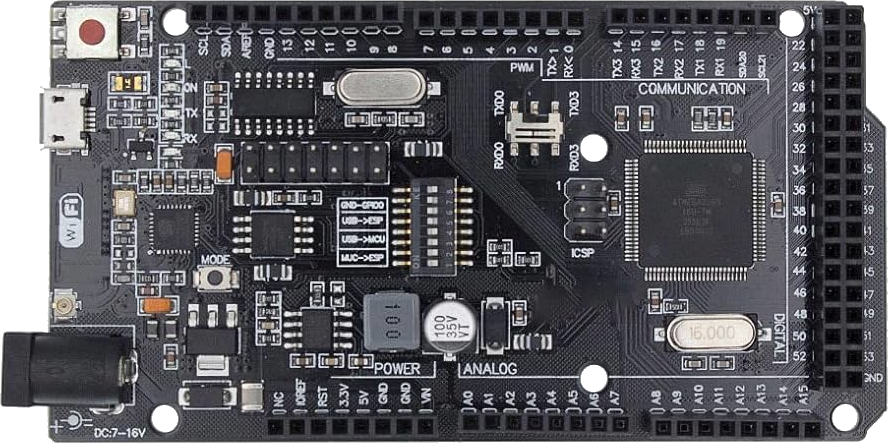
The Arduino Mega is a microcontroller board based on the ATmega2560, designed for projects requiring a large number of input/output pins and memory. The ESP8266 is a low-cost Wi-Fi module that enables wireless communication for IoT (Internet of Things) applications. When combined, the Arduino Mega and ESP8266 provide a powerful platform for building connected devices with extensive I/O capabilities and wireless connectivity.
Explore Projects Built with Arduino Mega & ESP8266
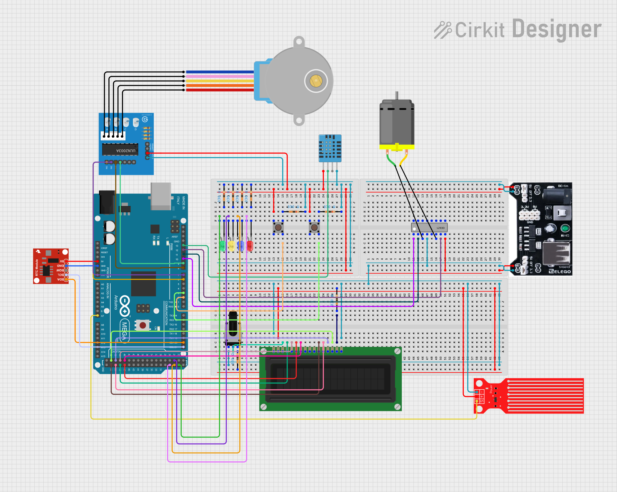
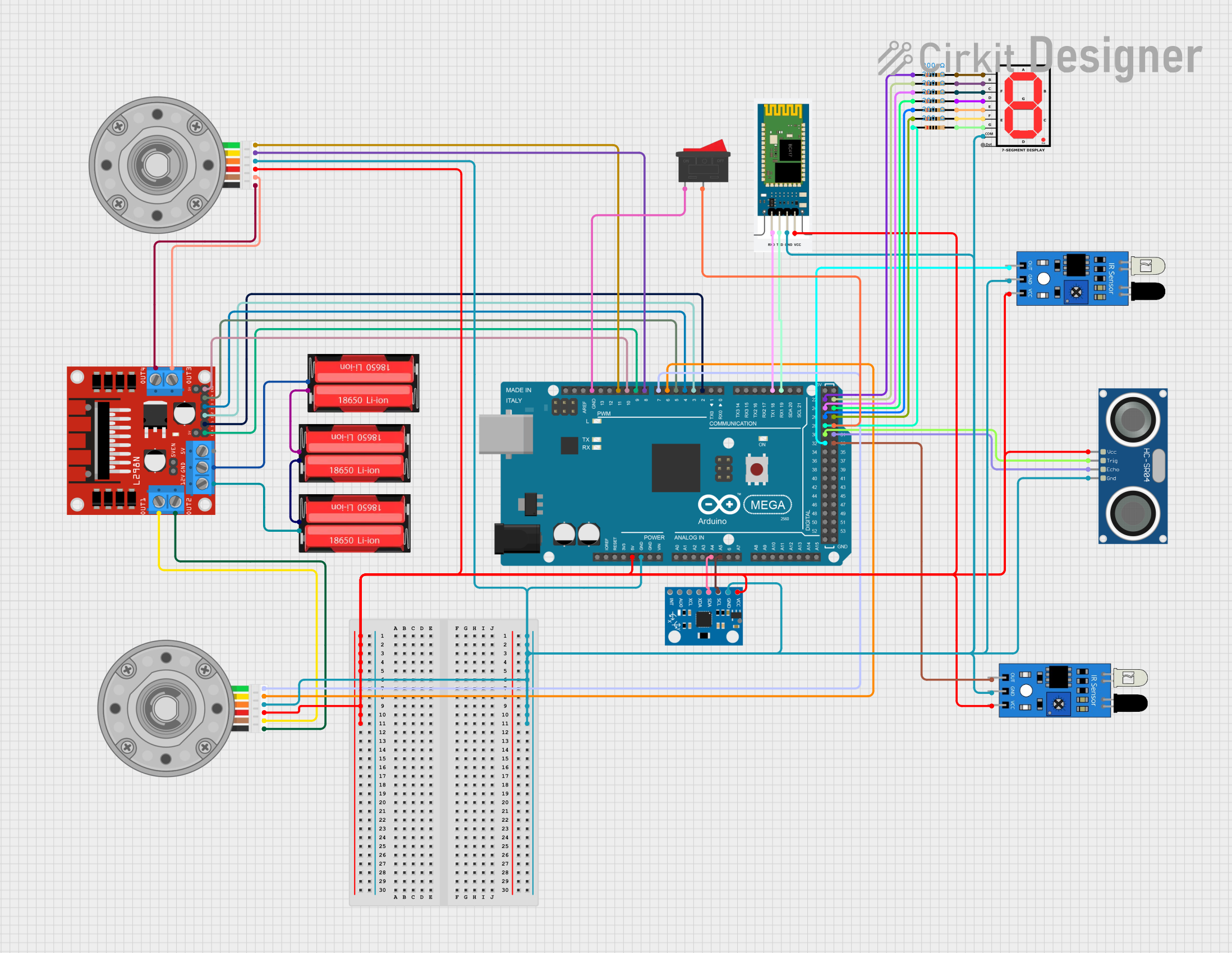
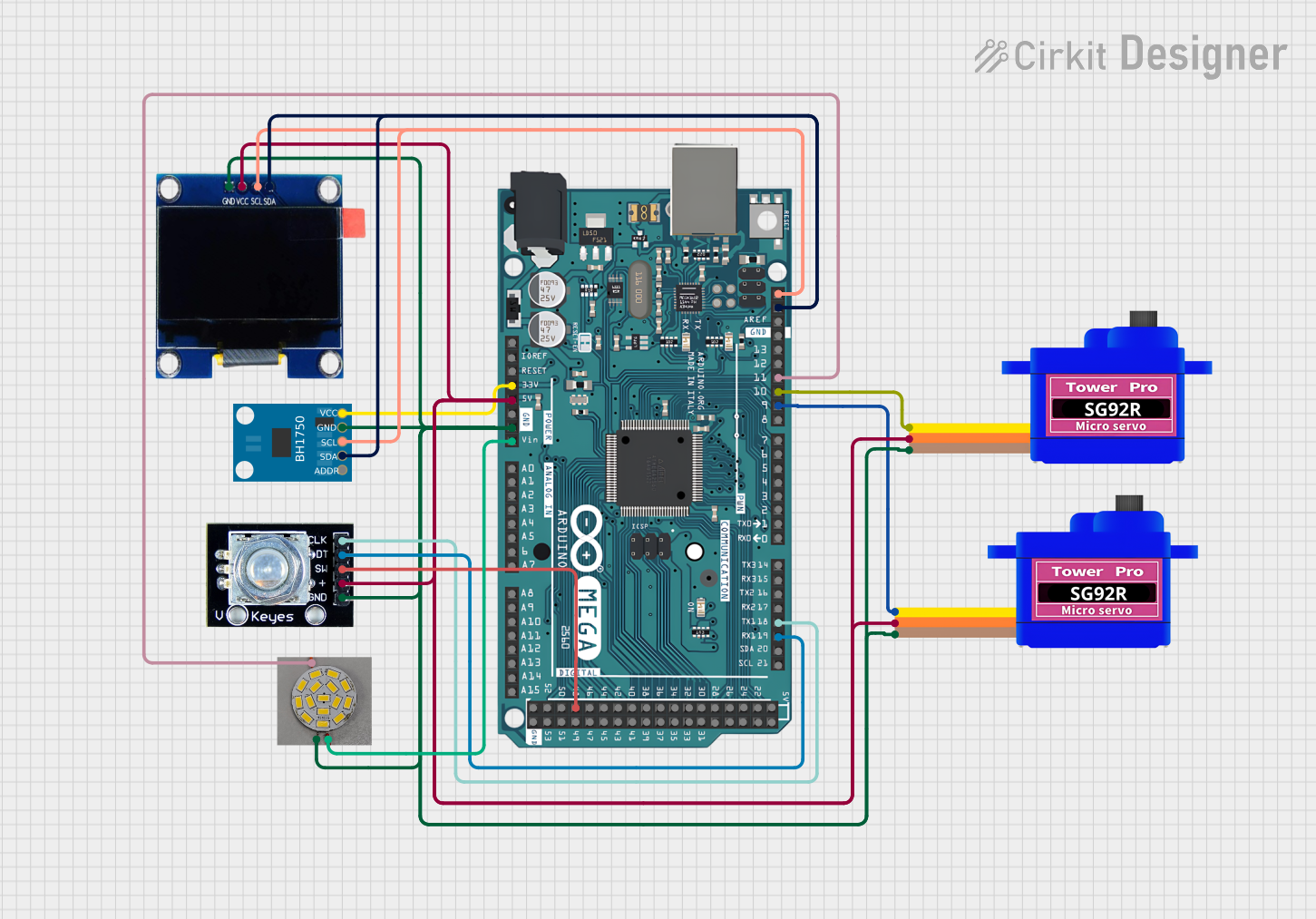
Explore Projects Built with Arduino Mega & ESP8266
Common Applications and Use Cases
- Home automation systems
- IoT devices and prototypes
- Wireless sensor networks
- Remote data logging and monitoring
- Smart appliances and robotics
Technical Specifications
Arduino Mega Specifications
| Parameter | Value |
|---|---|
| Microcontroller | ATmega2560 |
| Operating Voltage | 5V |
| Input Voltage (limits) | 6-20V |
| Digital I/O Pins | 54 (15 PWM outputs) |
| Analog Input Pins | 16 |
| Flash Memory | 256 KB (8 KB used by bootloader) |
| SRAM | 8 KB |
| EEPROM | 4 KB |
| Clock Speed | 16 MHz |
ESP8266 Specifications
| Parameter | Value |
|---|---|
| Operating Voltage | 3.3V |
| Wi-Fi Standard | 802.11 b/g/n |
| Flash Memory | 1 MB to 16 MB (varies by model) |
| GPIO Pins | Up to 17 (varies by model) |
| Communication Protocols | UART, SPI, I2C |
| Power Consumption | 15 µA (deep sleep), ~70 mA (active) |
Pin Configuration for ESP8266 (ESP-01 Module)
| Pin Name | Description |
|---|---|
| VCC | Power input (3.3V) |
| GND | Ground |
| TX | UART Transmit |
| RX | UART Receive |
| CH_PD | Chip Enable (connect to 3.3V for operation) |
| GPIO0 | General Purpose I/O (used for boot mode selection) |
| GPIO2 | General Purpose I/O |
| RST | Reset (active low) |
Usage Instructions
Connecting Arduino Mega to ESP8266
- Power Supply: Ensure the ESP8266 is powered with 3.3V. Do not connect it directly to the 5V pin of the Arduino Mega, as it may damage the module.
- Voltage Level Shifting: Use a voltage divider or level shifter for the TX pin of the Arduino Mega to step down the 5V signal to 3.3V for the ESP8266 RX pin.
- Wiring:
- Connect the ESP8266
VCCto a 3.3V power source. - Connect
GNDto the common ground of the Arduino Mega. - Connect the ESP8266
TXto the Arduino MegaRX1(pin 19). - Connect the ESP8266
RXto the Arduino MegaTX1(pin 18) through a voltage divider.
- Connect the ESP8266
Example Code for Arduino Mega with ESP8266
The following code demonstrates how to send AT commands to the ESP8266 and establish a Wi-Fi connection.
#include <SoftwareSerial.h>

// Define RX and TX pins for ESP8266 communication
#define RX_PIN 19  // Arduino Mega RX1
#define TX_PIN 18  // Arduino Mega TX1

void setup() {
  // Initialize Serial Monitor for debugging
  Serial.begin(9600);
  while (!Serial) {
    ; // Wait for Serial Monitor to open
  }
  Serial.println("Initializing ESP8266...");

  // Initialize Serial1 for ESP8266 communication
  Serial1.begin(115200); // Default baud rate for ESP8266
  delay(2000); // Allow time for ESP8266 to initialize

  // Test communication with ESP8266
  Serial1.println("AT"); // Send AT command
  delay(1000); // Wait for response
  while (Serial1.available()) {
    Serial.write(Serial1.read()); // Forward ESP8266 response to Serial Monitor
  }

  // Connect to Wi-Fi network
  Serial1.println("AT+CWJAP=\"YourSSID\",\"YourPassword\""); // Replace with your Wi-Fi credentials
  delay(5000); // Wait for connection
  while (Serial1.available()) {
    Serial.write(Serial1.read()); // Forward ESP8266 response to Serial Monitor
  }
}

void loop() {
  // Add your main code here
}
Important Considerations
- Power Supply: Ensure the ESP8266 receives a stable 3.3V power supply. Use a dedicated regulator if necessary.
- Baud Rate: The default baud rate for the ESP8266 is 115200. If communication issues occur, try changing the baud rate using the
AT+UARTcommand. - Connections: Double-check all connections, especially the voltage levels, to avoid damaging the ESP8266.
Troubleshooting and FAQs
Common Issues
ESP8266 Not Responding to AT Commands:
- Ensure the ESP8266 is powered correctly (3.3V).
- Verify the RX and TX connections between the Arduino Mega and ESP8266.
- Check the baud rate settings in the code.
Wi-Fi Connection Fails:
- Double-check the SSID and password in the
AT+CWJAPcommand. - Ensure the Wi-Fi network is within range and not using unsupported security protocols.
- Double-check the SSID and password in the
Garbage Characters in Serial Monitor:
- Ensure the Serial Monitor baud rate matches the Arduino Mega's
Serial.begin()setting. - Verify the ESP8266 baud rate matches the
Serial1.begin()setting.
- Ensure the Serial Monitor baud rate matches the Arduino Mega's
Tips for Troubleshooting
- Use an external USB-to-Serial adapter to test the ESP8266 independently of the Arduino Mega.
- If the ESP8266 firmware is outdated, consider updating it to the latest version for improved stability and features.
- Use a multimeter to verify voltage levels and continuity in your circuit.
By following this documentation, you can successfully integrate the Arduino Mega and ESP8266 into your projects, enabling powerful IoT applications with ease.