How to Use DRIVER: Examples, Pinouts, and Specs
Introduction
A driver is an essential electronic component designed to provide the necessary power and control signals to operate other components, such as motors, LEDs, or other high-power devices. Drivers act as intermediaries between control systems (e.g., microcontrollers) and the load, ensuring efficient operation by managing voltage, current, and signal levels. They are widely used in applications requiring precise control and high-power delivery.
Explore Projects Built with DRIVER
Explore Projects Built with DRIVER
Common Applications and Use Cases
- Driving DC motors, stepper motors, or servo motors in robotics and automation.
- Controlling high-power LEDs in lighting systems.
- Powering solenoids, relays, or other electromechanical devices.
- Interfacing microcontrollers with high-power loads in embedded systems.
Technical Specifications
The technical specifications of a driver can vary depending on its type and intended application. Below are general specifications for a typical motor driver IC (e.g., L298N Dual H-Bridge Motor Driver):
Key Technical Details
- Operating Voltage: 5V to 46V (depending on the driver type).
- Output Current: Up to 2A per channel (continuous), 3A peak.
- Control Logic Voltage: 3.3V or 5V (compatible with most microcontrollers).
- Number of Channels: Dual-channel (can drive two motors independently).
- Thermal Protection: Built-in over-temperature shutdown.
- Current Sensing: Optional pins for monitoring motor current.
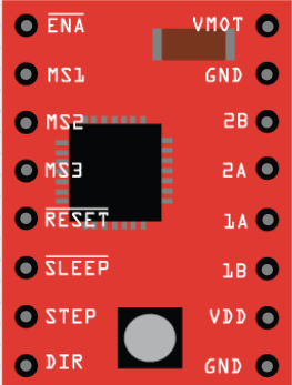
Pin Configuration and Descriptions
Below is the pin configuration for a typical L298N motor driver IC:
| Pin Name | Description |
|---|---|
| VCC | Power supply for the motor (e.g., 12V or 24V). |
| GND | Ground connection. |
| 5V | Logic voltage input (can be used to power the control logic). |
| IN1, IN2 | Control inputs for Motor 1 (used to set direction and speed). |
| IN3, IN4 | Control inputs for Motor 2 (used to set direction and speed). |
| ENA | Enable pin for Motor 1 (PWM input for speed control). |
| ENB | Enable pin for Motor 2 (PWM input for speed control). |
| OUT1, OUT2 | Output pins for Motor 1 (connect to motor terminals). |
| OUT3, OUT4 | Output pins for Motor 2 (connect to motor terminals). |
| CS1, CS2 | Current sensing pins for Motor 1 and Motor 2 (optional, for monitoring). |
Usage Instructions
How to Use the Component in a Circuit
- Power Connections: Connect the VCC pin to the motor's power supply (e.g., 12V or 24V) and the GND pin to the ground of the circuit.
- Logic Voltage: Provide 5V to the logic voltage pin (if required) or use the onboard regulator (if available).
- Control Inputs: Connect the IN1, IN2, IN3, and IN4 pins to the microcontroller's GPIO pins. These pins control the direction of the motors.
- Enable Pins: Use the ENA and ENB pins for speed control by providing a PWM signal from the microcontroller.
- Motor Outputs: Connect the motor terminals to the OUT1, OUT2, OUT3, and OUT4 pins.
- Optional Current Sensing: If current monitoring is needed, connect the CS1 and CS2 pins to an analog input on the microcontroller.
Important Considerations and Best Practices
- Ensure the motor's voltage and current ratings are within the driver's specifications.
- Use appropriate heat sinks or cooling mechanisms if the driver operates at high currents.
- Avoid short circuits between the output pins, as this can damage the driver.
- Use decoupling capacitors near the power supply pins to reduce noise and voltage spikes.
- If using an Arduino UNO, ensure the control pins are properly configured in the code.
Example Code for Arduino UNO
Below is an example code snippet to control a DC motor using the L298N driver and Arduino UNO:
// Define motor control pins
const int IN1 = 9;  // Motor 1 direction control pin
const int IN2 = 8;  // Motor 1 direction control pin
const int ENA = 10; // Motor 1 speed control (PWM) pin

void setup() {
  // Set motor control pins as outputs
  pinMode(IN1, OUTPUT);
  pinMode(IN2, OUTPUT);
  pinMode(ENA, OUTPUT);
}

void loop() {
  // Rotate motor in one direction
  digitalWrite(IN1, HIGH); // Set IN1 high
  digitalWrite(IN2, LOW);  // Set IN2 low
  analogWrite(ENA, 128);   // Set speed to 50% (PWM value: 128 out of 255)
  delay(2000);             // Run for 2 seconds

  // Stop the motor
  digitalWrite(IN1, LOW);  // Set IN1 low
  digitalWrite(IN2, LOW);  // Set IN2 low
  delay(1000);             // Wait for 1 second

  // Rotate motor in the opposite direction
  digitalWrite(IN1, LOW);  // Set IN1 low
  digitalWrite(IN2, HIGH); // Set IN2 high
  analogWrite(ENA, 128);   // Set speed to 50% (PWM value: 128 out of 255)
  delay(2000);             // Run for 2 seconds

  // Stop the motor
  digitalWrite(IN1, LOW);  // Set IN1 low
  digitalWrite(IN2, LOW);  // Set IN2 low
  delay(1000);             // Wait for 1 second
}
Troubleshooting and FAQs
Common Issues Users Might Face
Motor Not Spinning:
- Check the power supply connections to the driver and motor.
- Verify that the control signals (IN1, IN2, ENA, etc.) are correctly configured.
- Ensure the motor is functional and not damaged.
Driver Overheating:
- Ensure the current drawn by the motor does not exceed the driver's maximum rating.
- Use a heat sink or cooling fan if necessary.
Erratic Motor Behavior:
- Check for loose or faulty connections.
- Add decoupling capacitors to the power supply to reduce noise.
PWM Signal Not Working:
- Verify the PWM pin configuration in the microcontroller code.
- Ensure the PWM frequency is compatible with the driver.
Solutions and Tips for Troubleshooting
- Use a multimeter to check voltage levels at the driver's input and output pins.
- Test the driver with a simple circuit before integrating it into a complex system.
- Refer to the datasheet of the specific driver IC for detailed information and recommendations.