Cirkit Designer Logo
Cirkit Designer
Your all-in-one circuit design IDE
Home / 
Component Documentation

How to Use esp32: Examples, Pinouts, and Specs

Image of esp32
Cirkit Designer LogoDesign with esp32 in Cirkit Designer

Introduction

The ESP32, manufactured by Espressif Systems, is a low-cost, low-power system on a chip (SoC) with integrated Wi-Fi and Bluetooth capabilities. It is widely used in Internet of Things (IoT) applications, embedded systems, and smart devices due to its versatility, high performance, and energy efficiency. The ESP32 is based on a dual-core Xtensa LX6 microprocessor and includes a rich set of peripherals, making it suitable for a wide range of applications.

Explore Projects Built with esp32

Use Cirkit Designer to design, explore, and prototype these projects online. Some projects support real-time simulation. Click "Open Project" to start designing instantly!
ESP32-Controlled OLED Display and Servo with DotStar LED Strip and Audio Output
Image of Arena 2: A project utilizing esp32 in a practical application
This circuit features an ESP32 microcontroller driving a variety of components. It controls an OLED display for visual output, a DotStar LED strip for lighting effects, a PAM8403 audio amplifier connected to a speaker for sound output, and a PCA9685 PWM Servo Breakout to manage a servo motor. The ESP32 also interfaces with a piezo speaker for additional sound generation, and the circuit is powered by a 18650 Li-ion battery setup with a TP4056 charging module. The ESP32's embedded code handles the display animation on the OLED.
Cirkit Designer LogoOpen Project in Cirkit Designer
ESP32-Based Sensor Monitoring System with OLED Display and E-Stop
Image of MVP_design: A project utilizing esp32 in a practical application
This circuit features an ESP32 microcontroller that interfaces with a variety of sensors and output devices. It is powered by a Lipo battery through a buck converter, ensuring a stable voltage supply. The ESP32 collects data from a DHT11 temperature and humidity sensor and a vibration sensor, controls a buzzer, and displays information on an OLED screen. An emergency stop (E Stop) is connected for safety purposes, allowing the system to be quickly deactivated.
Cirkit Designer LogoOpen Project in Cirkit Designer
ESP32-Based Environmental Monitoring System with Motion Detection
Image of pro: A project utilizing esp32 in a practical application
This circuit features an ESP32 microcontroller on a baseboard that interfaces with a PIR sensor for motion detection, a DHT22 sensor for measuring temperature and humidity, and a BH1750 sensor for detecting ambient light levels. The ESP32 is configured to communicate with the BH1750 using I2C protocol, with GPIO22 and GPIO21 serving as the SCL and SDA lines, respectively. Power is supplied to the sensors from the ESP32's voltage output pins, and sensor outputs are connected to designated GPIO pins for data acquisition.
Cirkit Designer LogoOpen Project in Cirkit Designer
ESP32-Based Smart Weather Station with Wi-Fi Connectivity
Image of flowchart 3D: A project utilizing esp32 in a practical application
This circuit features an ESP32 microcontroller interfacing with various sensors and modules, including a DHT22 temperature and humidity sensor, an ESP32 CAM for image capture, an I2C LCD screen for display, a load cell with an HX711 interface for weight measurement, and a buzzer for audio alerts. The ESP32 handles data acquisition, processing, and communication with these peripherals to create a multi-functional monitoring and alert system.
Cirkit Designer LogoOpen Project in Cirkit Designer

Explore Projects Built with esp32

Use Cirkit Designer to design, explore, and prototype these projects online. Some projects support real-time simulation. Click "Open Project" to start designing instantly!
Image of Arena 2: A project utilizing esp32 in a practical application
ESP32-Controlled OLED Display and Servo with DotStar LED Strip and Audio Output
This circuit features an ESP32 microcontroller driving a variety of components. It controls an OLED display for visual output, a DotStar LED strip for lighting effects, a PAM8403 audio amplifier connected to a speaker for sound output, and a PCA9685 PWM Servo Breakout to manage a servo motor. The ESP32 also interfaces with a piezo speaker for additional sound generation, and the circuit is powered by a 18650 Li-ion battery setup with a TP4056 charging module. The ESP32's embedded code handles the display animation on the OLED.
Cirkit Designer LogoOpen Project in Cirkit Designer
Image of MVP_design: A project utilizing esp32 in a practical application
ESP32-Based Sensor Monitoring System with OLED Display and E-Stop
This circuit features an ESP32 microcontroller that interfaces with a variety of sensors and output devices. It is powered by a Lipo battery through a buck converter, ensuring a stable voltage supply. The ESP32 collects data from a DHT11 temperature and humidity sensor and a vibration sensor, controls a buzzer, and displays information on an OLED screen. An emergency stop (E Stop) is connected for safety purposes, allowing the system to be quickly deactivated.
Cirkit Designer LogoOpen Project in Cirkit Designer
Image of pro: A project utilizing esp32 in a practical application
ESP32-Based Environmental Monitoring System with Motion Detection
This circuit features an ESP32 microcontroller on a baseboard that interfaces with a PIR sensor for motion detection, a DHT22 sensor for measuring temperature and humidity, and a BH1750 sensor for detecting ambient light levels. The ESP32 is configured to communicate with the BH1750 using I2C protocol, with GPIO22 and GPIO21 serving as the SCL and SDA lines, respectively. Power is supplied to the sensors from the ESP32's voltage output pins, and sensor outputs are connected to designated GPIO pins for data acquisition.
Cirkit Designer LogoOpen Project in Cirkit Designer
Image of flowchart 3D: A project utilizing esp32 in a practical application
ESP32-Based Smart Weather Station with Wi-Fi Connectivity
This circuit features an ESP32 microcontroller interfacing with various sensors and modules, including a DHT22 temperature and humidity sensor, an ESP32 CAM for image capture, an I2C LCD screen for display, a load cell with an HX711 interface for weight measurement, and a buzzer for audio alerts. The ESP32 handles data acquisition, processing, and communication with these peripherals to create a multi-functional monitoring and alert system.
Cirkit Designer LogoOpen Project in Cirkit Designer

Common Applications and Use Cases

  • IoT devices and smart home automation
  • Wearable electronics
  • Wireless sensor networks
  • Industrial automation
  • Robotics and drones
  • Prototyping and development of connected devices

Technical Specifications

The ESP32 (WROOM-32) module offers a comprehensive set of features and specifications that make it a powerful choice for developers.

Key Technical Details

Specification Value
Microcontroller Dual-core Xtensa LX6
Clock Speed Up to 240 MHz
Flash Memory 4 MB (external SPI flash)
SRAM 520 KB
Wi-Fi 802.11 b/g/n (2.4 GHz)
Bluetooth Bluetooth 4.2 and BLE
Operating Voltage 3.0V to 3.6V
GPIO Pins 34
ADC Channels 18 (12-bit resolution)
DAC Channels 2
Communication Interfaces UART, SPI, I2C, I2S, CAN, PWM
Power Consumption (Active) ~160 mA (Wi-Fi active)
Deep Sleep Current ~10 µA
Operating Temperature Range -40°C to +85°C
Dimensions 18 mm x 25.5 mm

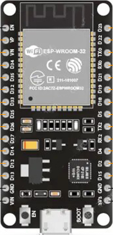
Pin Configuration and Descriptions

The ESP32 WROOM-32 module has 38 pins. Below is a summary of the key pins and their functions:

Pin Number Pin Name Description
1 EN Enable pin. Active high to enable the chip.
2 IO0 GPIO0. Used for boot mode selection.
3 IO2 GPIO2. General-purpose I/O.
4 IO4 GPIO4. General-purpose I/O.
5 IO5 GPIO5. General-purpose I/O.
6 IO12 GPIO12. General-purpose I/O.
7 IO13 GPIO13. General-purpose I/O.
8 IO14 GPIO14. General-purpose I/O.
9 IO15 GPIO15. General-purpose I/O.
10 IO16 GPIO16. General-purpose I/O.
11 IO17 GPIO17. General-purpose I/O.
12 GND Ground pin.
13 3V3 3.3V power supply.
14 TXD0 UART0 Transmit pin.
15 RXD0 UART0 Receive pin.

For a complete pinout diagram, refer to the official Espressif datasheet.

Usage Instructions

How to Use the ESP32 in a Circuit

  1. Power Supply: Provide a stable 3.3V power supply to the 3V3 pin. Ensure the current rating of the power source is sufficient for the ESP32's operation, especially during Wi-Fi transmission.
  2. Boot Mode: To upload code, connect GPIO0 to GND and reset the module. After uploading, disconnect GPIO0 from GND.
  3. Connections: Use the UART pins (TXD0 and RXD0) for serial communication with a computer or microcontroller. Connect peripherals to the GPIO pins as needed.
  4. Programming: The ESP32 can be programmed using the Arduino IDE, Espressif's ESP-IDF, or other development environments.

Important Considerations and Best Practices

  • Voltage Levels: The ESP32 operates at 3.3V logic levels. Avoid connecting 5V signals directly to its GPIO pins.
  • Decoupling Capacitors: Place decoupling capacitors near the power pins to ensure stable operation.
  • Antenna Placement: Ensure the onboard antenna has sufficient clearance from metal objects to avoid interference.
  • Deep Sleep Mode: Use deep sleep mode to conserve power in battery-powered applications.

Example Code for Arduino UNO

Below is an example of how to blink an LED connected to GPIO2 of the ESP32 using the Arduino IDE:

// Example: Blink an LED connected to GPIO2 of the ESP32

#define LED_PIN 2  // GPIO2 is connected to the LED

void setup() {
  pinMode(LED_PIN, OUTPUT);  // Set GPIO2 as an output pin
}

void loop() {
  digitalWrite(LED_PIN, HIGH);  // Turn the LED on
  delay(1000);                 // Wait for 1 second
  digitalWrite(LED_PIN, LOW);   // Turn the LED off
  delay(1000);                 // Wait for 1 second
}

Troubleshooting and FAQs

Common Issues and Solutions

  1. ESP32 Not Detected by Computer:

    • Ensure the correct USB driver for the ESP32 is installed.
    • Check the USB cable for damage or try a different cable.
    • Verify that the ESP32 is in boot mode when uploading code.
  2. Wi-Fi Connection Fails:

    • Double-check the SSID and password in your code.
    • Ensure the Wi-Fi network is operating on the 2.4 GHz band (ESP32 does not support 5 GHz).
  3. GPIO Pins Not Responding:

    • Verify that the pins are not being used by other peripherals (e.g., ADC, UART).
    • Check for proper pull-up or pull-down resistors if required.
  4. High Power Consumption:

    • Use deep sleep mode to reduce power consumption in battery-powered applications.
    • Disable unused peripherals in your code.

FAQs

Q: Can the ESP32 be powered directly from a 5V source?
A: No, the ESP32 operates at 3.3V. Use a voltage regulator to step down 5V to 3.3V.

Q: How many devices can the ESP32 connect to via Bluetooth?
A: The ESP32 supports up to 7 simultaneous Bluetooth connections in classic mode.

Q: Can I use the ESP32 with a 5V logic microcontroller?
A: Yes, but you will need level shifters to safely interface the 5V logic with the ESP32's 3.3V logic.

Q: What is the maximum range of the ESP32's Wi-Fi?
A: The range depends on environmental factors but is typically up to 100 meters in open space.

For additional support, refer to the official Espressif documentation or community forums.