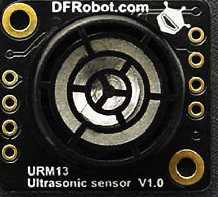
How to Use URM13 Ultrasonic Sensor: Examples, Pinouts, and Specs
Introduction
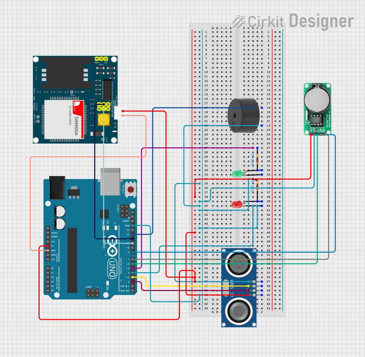
The URM13 Ultrasonic Sensor (Manufacturer Part ID: SEN0352) by DFRobot is a high-performance distance measuring device that utilizes ultrasonic waves to determine the distance to an object. By emitting sound waves and measuring the time it takes for the echo to return, the URM13 provides accurate and reliable distance measurements. This sensor is ideal for applications such as robotics, obstacle detection, industrial automation, and smart systems.
Explore Projects Built with URM13 Ultrasonic Sensor
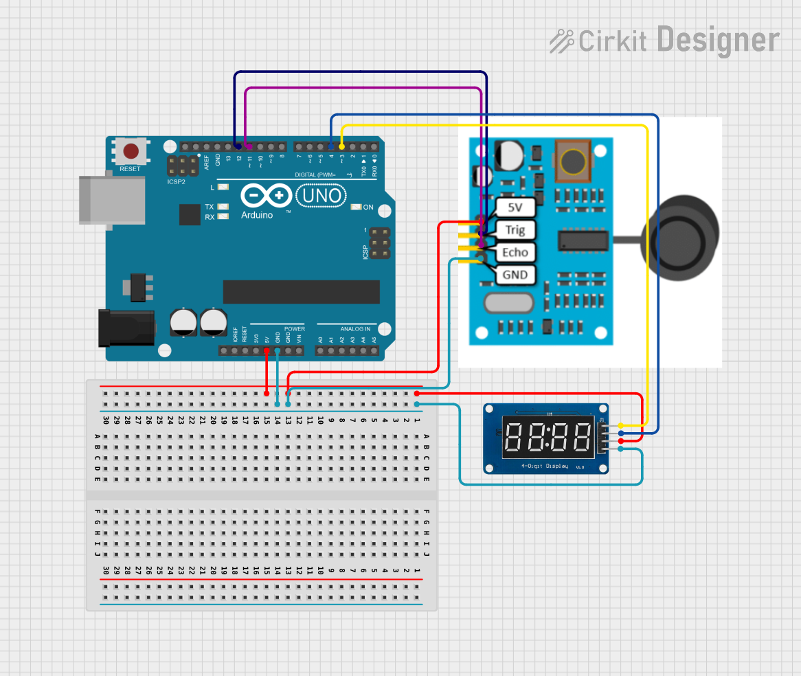
Explore Projects Built with URM13 Ultrasonic Sensor
Common Applications
- Obstacle detection in robotics
- Distance measurement in industrial automation
- Smart parking systems
- Liquid level detection
- Proximity sensing in security systems
Technical Specifications
The URM13 Ultrasonic Sensor is designed for precision and versatility. Below are its key technical details:
| Parameter | Value |
|---|---|
| Operating Voltage | 3.3V to 5V |
| Operating Current | ≤20mA |
| Measuring Range | 20mm to 5000mm (2cm to 5m) |
| Accuracy | ±1% of the measured distance |
| Communication Interface | UART (default) or I2C |
| Operating Temperature | -10°C to 70°C |
| Beam Angle | 60° |
| Dimensions | 22mm x 22mm x 30mm |
Pin Configuration
The URM13 Ultrasonic Sensor has a 4-pin interface. The pinout is as follows:
| Pin | Name | Description |
|---|---|---|
| 1 | VCC | Power supply input (3.3V to 5V) |
| 2 | GND | Ground connection |
| 3 | TX/SCL | UART TX (default) or I2C SCL (configurable) |
| 4 | RX/SDA | UART RX (default) or I2C SDA (configurable) |
Usage Instructions
The URM13 Ultrasonic Sensor is easy to integrate into a variety of projects. Below are the steps to use it effectively:
Connecting the Sensor
- Power Supply: Connect the VCC pin to a 3.3V or 5V power source and the GND pin to ground.
- Communication Interface:
- For UART mode (default): Connect the TX pin to the RX pin of your microcontroller and the RX pin to the TX pin of your microcontroller.
- For I2C mode: Connect the SCL pin to the I2C clock line and the SDA pin to the I2C data line. Ensure pull-up resistors are used if required.
Using the Sensor with Arduino UNO
The following example demonstrates how to use the URM13 in UART mode with an Arduino UNO to measure distance:
#include <SoftwareSerial.h>

// Define the pins for SoftwareSerial
SoftwareSerial URM13(10, 11); // RX = Pin 10, TX = Pin 11

void setup() {
  Serial.begin(9600);         // Initialize Serial Monitor
  URM13.begin(9600);          // Initialize URM13 communication at 9600 baud
  Serial.println("URM13 Ultrasonic Sensor Initialized");
}

void loop() {
  // Request distance measurement
  URM13.write(0x55);          // Send command to request distance
  delay(100);                 // Wait for the sensor to process

  // Read the response (2 bytes for distance in mm)
  if (URM13.available() >= 2) {
    uint8_t highByte = URM13.read(); // Read high byte
    uint8_t lowByte = URM13.read();  // Read low byte
    int distance = (highByte << 8) | lowByte; // Combine bytes into distance

    // Print the distance to the Serial Monitor
    Serial.print("Distance: ");
    Serial.print(distance);
    Serial.println(" mm");
  }

  delay(500); // Wait before the next measurement
}
Important Considerations
- Power Supply: Ensure the sensor is powered within its operating voltage range (3.3V to 5V).
- Beam Angle: The sensor has a 60° beam angle, so ensure there are no obstructions within this range that could interfere with measurements.
- Mode Configuration: The sensor defaults to UART mode. To switch to I2C mode, refer to the manufacturer's configuration instructions.
- Environmental Factors: Ultrasonic sensors may be affected by temperature, humidity, and soft surfaces that absorb sound waves.
Troubleshooting and FAQs
Common Issues and Solutions
No Response from the Sensor:
- Verify the power supply connections (VCC and GND).
- Ensure the communication interface (UART or I2C) is correctly configured.
- Check the baud rate (default is 9600 for UART).
Inaccurate Distance Measurements:
- Ensure the target object is within the sensor's measuring range (20mm to 5000mm).
- Avoid using the sensor in environments with excessive noise or vibrations.
- Check for obstructions within the 60° beam angle.
Interference with Other Ultrasonic Sensors:
- If multiple ultrasonic sensors are used, ensure they are triggered at different times to avoid cross-interference.
FAQs
Q: Can the URM13 detect transparent objects?
A: Ultrasonic sensors may struggle with transparent objects like glass, as sound waves can pass through or reflect unpredictably. For best results, use opaque targets.
Q: How do I switch between UART and I2C modes?
A: The URM13 defaults to UART mode. To switch to I2C mode, refer to the DFRobot documentation for the specific configuration commands.
Q: What is the maximum cable length for the sensor?
A: For UART mode, keep the cable length under 1 meter to avoid signal degradation. For I2C mode, use appropriate pull-up resistors and keep the cable length as short as possible.
By following this documentation, you can effectively integrate the URM13 Ultrasonic Sensor into your projects for accurate and reliable distance measurements.