How to Use Rotary Encoder: Examples, Pinouts, and Specs
Introduction
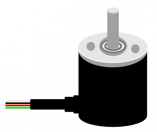
A rotary encoder is an electro-mechanical device that converts the angular position or motion of a shaft or axle to an analog or digital output signal. Rotary encoders are widely used in various applications such as industrial controls, robotics, computer input devices (like volume controls and scrolling), and more. They are favored for their precision and the ability to provide unlimited rotation compared to potentiometers which have a limited range of motion.
Explore Projects Built with Rotary Encoder
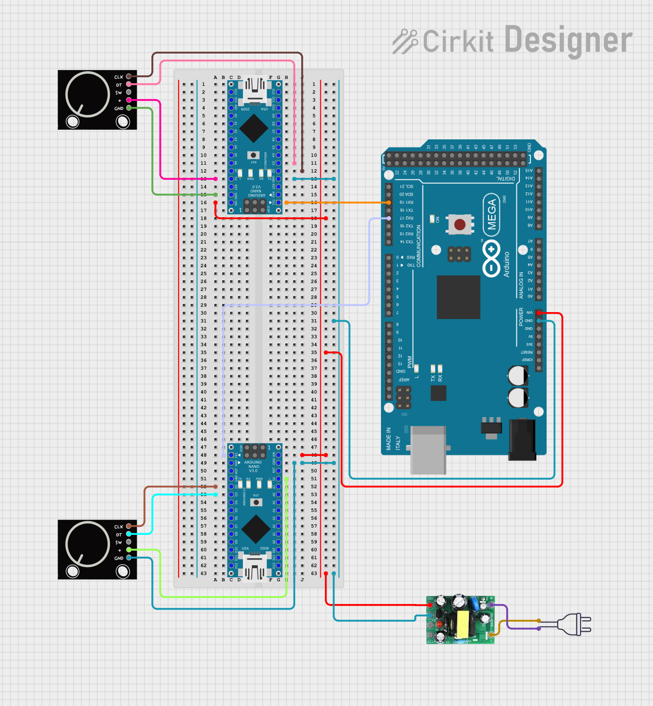
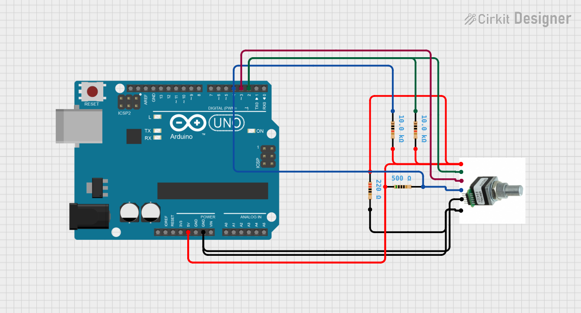
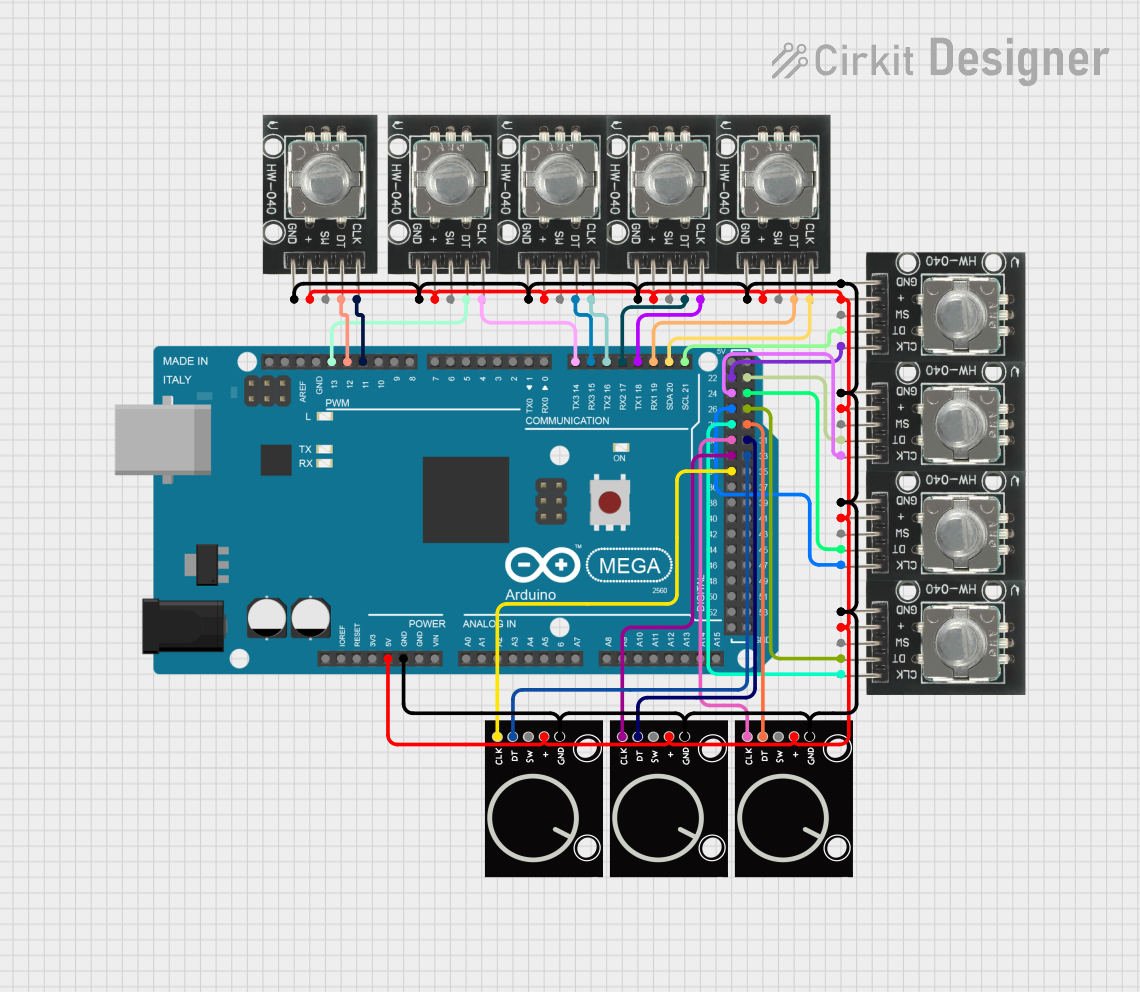
Explore Projects Built with Rotary Encoder
Technical Specifications
Key Technical Details
- Type: Incremental or Absolute
- Output: Analog (Potentiometric) or Digital (Quadrature)
- Resolution: Number of pulses per revolution (PPR)
- Supply Voltage: Typically 3.3V to 5V
- Current Rating: Depends on the model, usually in the range of 10mA to 50mA
- Operating Temperature: Varies with model, e.g., -40°C to +85°C
Pin Configuration and Descriptions
| Pin Number | Name | Description |
|---|---|---|
| 1 | Vcc | Power supply (3.3V to 5V) |
| 2 | GND | Ground connection |
| 3 | SW | Push-button switch (active low) |
| 4 | DT | Data or B phase |
| 5 | CLK | Clock or A phase |
Usage Instructions
Connecting to a Circuit
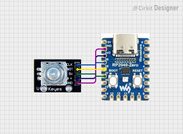
To use a rotary encoder with a microcontroller like an Arduino UNO, connect the pins as follows:
- Vcc to 5V (or 3.3V if applicable)
- GND to ground
- SW to a digital input pin (with an optional pull-up resistor)
- DT to another digital input pin
- CLK to another digital input pin
Best Practices
- Use internal or external pull-up resistors on the DT and CLK pins to ensure stable readings.
- Debounce the rotary encoder in software to prevent false readings due to mechanical noise.
- Implement an interrupt service routine (ISR) for handling the encoder's rotation to ensure no pulses are missed.
Example Code for Arduino UNO
// Define the connections to the Arduino
const int pinA = 2; // CLK
const int pinB = 3; // DT
const int buttonPin = 4; // SW

volatile int encoderValue = 0;
int lastEncoded = 0;

void setup() {
  pinMode(pinA, INPUT_PULLUP);
  pinMode(pinB, INPUT_PULLUP);
  pinMode(buttonPin, INPUT_PULLUP);
  attachInterrupt(digitalPinToInterrupt(pinA), updateEncoder, CHANGE);
  attachInterrupt(digitalPinToInterrupt(pinB), updateEncoder, CHANGE);
  Serial.begin(9600);
}

void loop() {
  // Use encoderValue in your application
  Serial.println(encoderValue);
  delay(100);
}

void updateEncoder() {
  int MSB = digitalRead(pinA); // MSB = most significant bit
  int LSB = digitalRead(pinB); // LSB = least significant bit

  int encoded = (MSB << 1) | LSB; // converting the 2 pin value to single number
  int sum = (lastEncoded << 2) | encoded; // adding it to the previous encoded value

  if(sum == 0b1101 || sum == 0b0100 || sum == 0b0010 || sum == 0b1011) encoderValue ++;
  if(sum == 0b1110 || sum == 0b0111 || sum == 0b0001 || sum == 0b1000) encoderValue --;

  lastEncoded = encoded; // store this value for next time
}
Troubleshooting and FAQs
Common Issues
- Jittery or Inconsistent Readings: This is often due to a lack of debouncing. Implement software debouncing or use hardware debouncing circuits.
- Missed Steps: If the encoder is being turned very quickly, steps may be missed. Use interrupts in your code to catch every change.
- No Response: Ensure that the encoder is powered correctly and that all connections are secure. Check for any damage to the encoder.
FAQs
Q: Can I use a rotary encoder for precise positioning? A: Yes, but for very precise applications, an absolute encoder or a high-resolution incremental encoder with an appropriate algorithm is recommended.
Q: How do I know if my rotary encoder is incremental or absolute? A: Incremental encoders provide relative position with no fixed start or end point, while absolute encoders provide a unique position value from the start of rotation.
Q: What is the difference between a rotary encoder and a potentiometer? A: A rotary encoder can rotate indefinitely and usually provides digital signals, while a potentiometer has a limited rotation and provides an analog signal.
Q: How can I detect the direction of rotation? A: By comparing the sequence of high and low signals from the DT and CLK pins, you can determine the direction of rotation. This is demonstrated in the example code provided.
Q: What is the purpose of the SW pin on the rotary encoder? A: The SW pin is connected to a push-button switch built into the rotary encoder. It can be used as a user input button, often to select an option or confirm a choice.