How to Use RM3100 Magnetometer: Examples, Pinouts, and Specs
Introduction
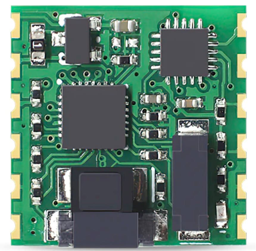
The RM3100 is a high-performance 3-axis magnetometer manufactured by Drotek, designed to provide precise magnetic field measurements. It is widely used in applications such as navigation, robotics, geophysical surveys, and attitude control systems. The RM3100 stands out for its digital output, low power consumption, and high sensitivity, making it ideal for environments requiring accurate magnetic field detection.
Explore Projects Built with RM3100 Magnetometer
Explore Projects Built with RM3100 Magnetometer
Common Applications
- Navigation systems (e.g., drones, autonomous vehicles)
- Robotics for orientation and heading determination
- Geophysical surveys and magnetic anomaly detection
- Attitude and heading reference systems (AHRS)
- Consumer electronics with compass functionality
Technical Specifications
The RM3100 magnetometer is built for precision and efficiency. Below are its key technical details:
Key Specifications
| Parameter | Value |
|---|---|
| Manufacturer Part ID | RM3100 |
| Measurement Axes | 3 (X, Y, Z) |
| Magnetic Field Range | ±800 µT |
| Resolution | 0.015 µT |
| Interface | I²C, SPI |
| Supply Voltage | 2.4V to 3.6V |
| Operating Current | 8 mA (typical) |
| Standby Current | 2 µA |
| Operating Temperature | -40°C to +85°C |
| Output Data Rate | Configurable (up to 600 Hz) |
| Package Type | 24-pin QFN |
Pin Configuration
The RM3100 is typically integrated into a breakout board for ease of use. Below is the pin configuration for the RM3100 breakout board:
| Pin Number | Pin Name | Description |
|---|---|---|
| 1 | VDD | Power supply input (2.4V to 3.6V) |
| 2 | GND | Ground |
| 3 | SCL | I²C clock line |
| 4 | SDA | I²C data line |
| 5 | CS | Chip select for SPI |
| 6 | SCLK | SPI clock line |
| 7 | MISO | SPI master-in/slave-out |
| 8 | MOSI | SPI master-out/slave-in |
| 9-24 | NC | Not connected |
Usage Instructions
The RM3100 magnetometer can be used in a variety of circuits and systems. Below are the steps and considerations for integrating it into your project.
Connecting the RM3100 to an Arduino UNO
The RM3100 can communicate with an Arduino UNO using the I²C interface. Follow these steps to connect and use the RM3100:
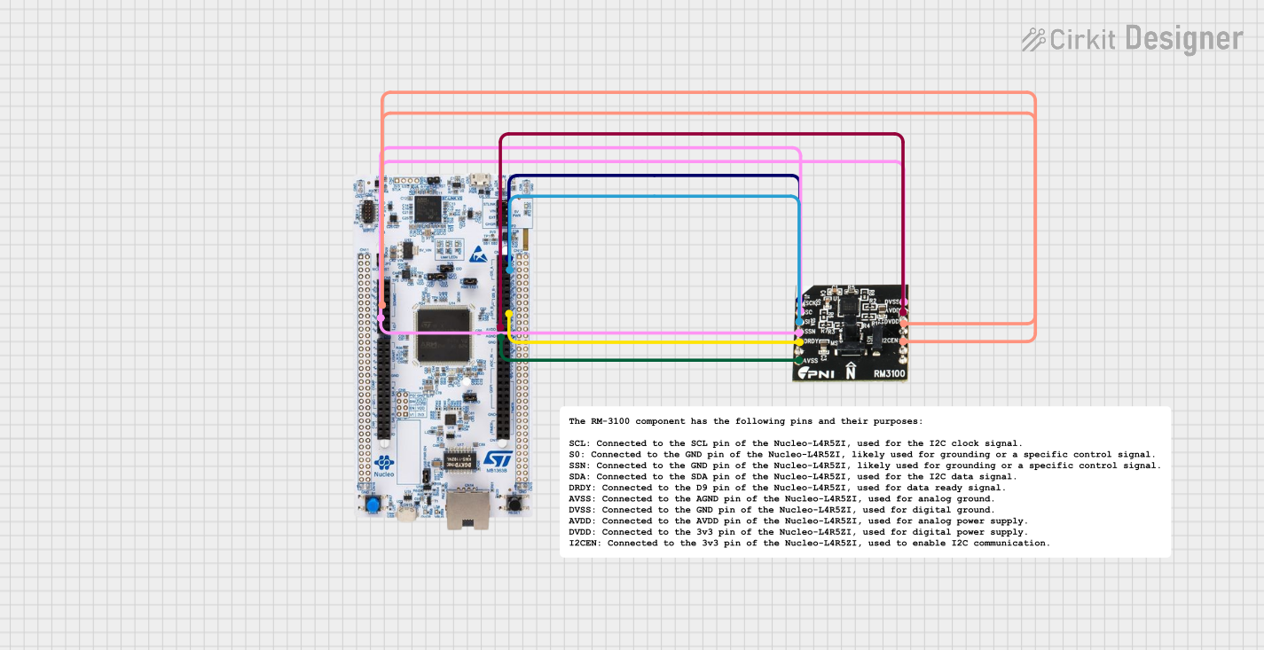
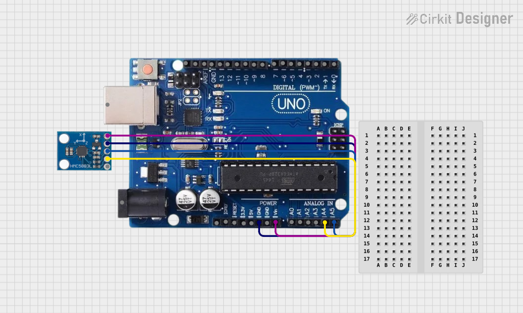
Wiring:
- Connect the RM3100's
VDDpin to the Arduino's3.3Vpin. - Connect the
GNDpin to the Arduino'sGND. - Connect the
SCLpin to the Arduino'sA5pin (I²C clock line). - Connect the
SDApin to the Arduino'sA4pin (I²C data line).
- Connect the RM3100's
Install Required Libraries:
- Use an I²C library such as
Wire.hfor communication. - Optionally, check for RM3100-specific libraries available in the Arduino IDE Library Manager.
- Use an I²C library such as
Arduino Code Example: Below is an example code snippet to read data from the RM3100 using I²C:
#include <Wire.h>

// RM3100 I²C address (default)
#define RM3100_ADDRESS 0x20

void setup() {
  Wire.begin(); // Initialize I²C communication
  Serial.begin(9600); // Start serial communication for debugging

  // Initialize RM3100 (example configuration)
  Wire.beginTransmission(RM3100_ADDRESS);
  Wire.write(0x01); // Example register to configure
  Wire.write(0x70); // Example configuration value
  Wire.endTransmission();

  Serial.println("RM3100 initialized.");
}

void loop() {
  // Request data from RM3100
  Wire.beginTransmission(RM3100_ADDRESS);
  Wire.write(0x00); // Register to read data
  Wire.endTransmission();

  Wire.requestFrom(RM3100_ADDRESS, 6); // Request 6 bytes (X, Y, Z data)
  if (Wire.available() == 6) {
    int16_t x = (Wire.read() << 8) | Wire.read(); // Combine MSB and LSB
    int16_t y = (Wire.read() << 8) | Wire.read();
    int16_t z = (Wire.read() << 8) | Wire.read();

    // Print magnetic field values
    Serial.print("X: "); Serial.print(x);
    Serial.print(" Y: "); Serial.print(y);
    Serial.print(" Z: "); Serial.println(z);
  }

  delay(100); // Delay for readability
}
Important Considerations
- Power Supply: Ensure the RM3100 is powered with a stable 3.3V source. Avoid connecting it directly to a 5V supply.
- Pull-Up Resistors: The I²C lines (
SCLandSDA) may require external pull-up resistors (typically 4.7kΩ) if not already included on the breakout board. - Magnetic Interference: Avoid placing the RM3100 near ferromagnetic materials or strong magnetic fields, as they can affect accuracy.
- Calibration: Perform a calibration routine to account for hard and soft iron distortions in your environment.
Troubleshooting and FAQs
Common Issues
No Data Output:
- Cause: Incorrect wiring or I²C address mismatch.
- Solution: Double-check the connections and ensure the correct I²C address is used in the code.
Inaccurate Measurements:
- Cause: Magnetic interference or lack of calibration.
- Solution: Move the RM3100 away from magnetic sources and perform a calibration routine.
Device Not Detected:
- Cause: Missing pull-up resistors on I²C lines.
- Solution: Add 4.7kΩ pull-up resistors to the
SCLandSDAlines.
FAQs
Can the RM3100 be used with a 5V microcontroller?
- Yes, but you must use a level shifter to convert the 5V logic to 3.3V for the RM3100.
What is the maximum cable length for I²C communication?
- The maximum length depends on the pull-up resistor values and the I²C clock speed. For standard setups, keep the cable length under 1 meter.
How do I calibrate the RM3100?
- Calibration involves rotating the sensor in all directions to map the magnetic field. Use software tools or algorithms to compute the calibration parameters.
By following this documentation, you can effectively integrate and use the RM3100 magnetometer in your projects.