How to Use iot:bit: Examples, Pinouts, and Specs
Introduction
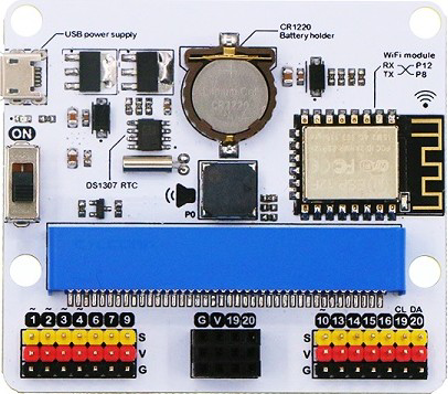
The iot:bit by ELECFREAKS is a compact microcontroller designed specifically for educational purposes and IoT (Internet of Things) projects. It features built-in sensors, LED lights, and multiple connectivity options, making it an excellent choice for beginners and advanced users alike. The iot:bit is compatible with micro:bit boards, enabling seamless integration into various projects.
Explore Projects Built with iot:bit


Explore Projects Built with iot:bit
Common Applications and Use Cases
- IoT-based educational projects
- Smart home automation systems
- Environmental monitoring (e.g., temperature, humidity)
- Robotics and interactive devices
- Prototyping for connected devices
Technical Specifications
Below are the key technical details of the iot:bit:
| Specification | Details |
|---|---|
| Manufacturer | ELECFREAKS |
| Part ID | iot:bit |
| Input Voltage | 3.3V to 5V |
| Communication Protocols | I2C, UART |
| Connectivity Options | Wi-Fi (via ESP8266 module), Bluetooth (via micro:bit) |
| Built-in Sensors | Light sensor, Sound sensor |
| Output Components | RGB LED (programmable), Buzzer |
| Expansion Ports | 4x Grove connectors, 1x I2C port |
| Dimensions | 65mm x 50mm x 15mm |
| Compatibility | micro:bit V1 and V2 |
Pin Configuration and Descriptions
The iot:bit features multiple ports and pins for connecting external components. Below is the pin configuration:
| Pin/Port | Description |
|---|---|
| Grove Port 1 | Analog/Digital input/output for external sensors or actuators |
| Grove Port 2 | Analog/Digital input/output for external sensors or actuators |
| Grove Port 3 | I2C communication port for connecting I2C-compatible devices |
| Grove Port 4 | UART communication port for serial devices |
| I2C Port | Dedicated I2C port for additional peripherals |
| RGB LED | Programmable RGB LED for visual feedback |
| Buzzer | Built-in buzzer for sound output |
| Power Input | Micro-USB or battery input (via micro:bit) |
Usage Instructions
How to Use the iot:bit in a Circuit
- Attach the micro:bit: Insert the micro:bit into the iot:bit's edge connector, ensuring proper alignment.
- Power the iot:bit: Connect a micro-USB cable or use a battery pack to power the device.
- Connect peripherals: Use the Grove connectors or I2C port to attach external sensors or actuators.
- Program the micro:bit: Write and upload code to the micro:bit using the MakeCode editor or Python.
Important Considerations and Best Practices
- Ensure the micro:bit is securely connected to the iot:bit to avoid communication issues.
- Use the correct Grove port for your sensor or actuator (e.g., I2C devices should connect to the I2C port).
- Avoid exceeding the input voltage range (3.3V to 5V) to prevent damage to the device.
- When using Wi-Fi, ensure the ESP8266 module is properly configured for your network.
Example Code for micro:bit (MakeCode)
Below is an example of how to control the RGB LED and read data from a light sensor using the MakeCode editor:
// Import the iot:bit extension in MakeCode before using this code

// Set the RGB LED to red
iotbit.setRGBLED(255, 0, 0) // Red: 255, Green: 0, Blue: 0

// Read light sensor data and display it on the micro:bit screen
basic.forever(function () {
    let lightLevel = iotbit.getLightLevel() // Get light sensor value
    basic.showNumber(lightLevel) // Display the light level on the LED matrix
    basic.pause(1000) // Wait for 1 second before updating
})
Example Code for micro:bit (Python)
Below is an example of how to control the buzzer and read data from the sound sensor using Python:
from microbit import *
import iotbit
Play a tone on the buzzer
iotbit.buzzer_on(440) # Play a 440 Hz tone sleep(1000) # Wait for 1 second iotbit.buzzer_off() # Turn off the buzzer
Continuously read sound sensor data
while True: sound_level = iotbit.get_sound_level() # Get sound sensor value display.scroll(str(sound_level)) # Display the sound level on the LED matrix sleep(1000) # Wait for 1 second
Troubleshooting and FAQs
Common Issues and Solutions
The iot:bit is not powering on:
- Ensure the micro:bit is properly inserted into the edge connector.
- Check the power source (micro-USB cable or battery pack) for proper connection.
Sensors are not responding:
- Verify that the sensors are connected to the correct Grove port.
- Check the sensor's compatibility with the iot:bit and ensure proper wiring.
Wi-Fi connectivity issues:
- Ensure the ESP8266 module is configured with the correct SSID and password.
- Check for interference or weak Wi-Fi signals in the area.
RGB LED or buzzer not working:
- Confirm that the correct commands are being sent in the code.
- Check for any short circuits or loose connections.
FAQs
Q: Can I use the iot:bit without a micro:bit?
A: No, the iot:bit is designed to work as an expansion board for the micro:bit and requires it for operation.
Q: What programming languages are supported?
A: The iot:bit supports MakeCode (block-based programming) and Python for coding.
Q: Can I connect multiple I2C devices to the iot:bit?
A: Yes, the I2C port supports multiple devices as long as they have unique addresses.
Q: Is the iot:bit compatible with micro:bit V2?
A: Yes, the iot:bit is compatible with both micro:bit V1 and V2.
For additional support, refer to the official ELECFREAKS documentation or community forums.