How to Use 24V SINGLE CHANNEL RELAY: Examples, Pinouts, and Specs
Introduction
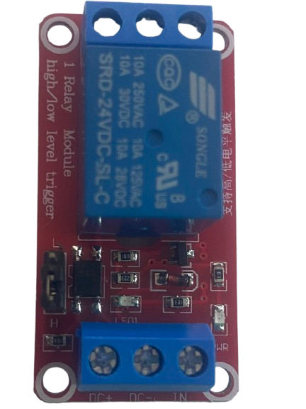
The 24V Single Channel Relay is an electromechanical switch that operates at 24 volts, enabling a low-power control circuit to manage a higher power circuit. This relay is commonly used in applications where electrical isolation and high-power switching are required. It features a single set of contacts (commonly SPDT or SPST) that can be opened or closed to control the connected load.
Explore Projects Built with 24V SINGLE CHANNEL RELAY


Explore Projects Built with 24V SINGLE CHANNEL RELAY
Common Applications and Use Cases
- Home automation systems
- Industrial control systems
- Motor control
- Lighting control
- IoT projects
- Interfacing microcontrollers (e.g., Arduino, Raspberry Pi) with high-power devices
Technical Specifications
Below are the key technical details of the 24V Single Channel Relay:
| Parameter | Value |
|---|---|
| Operating Voltage | 24V DC |
| Trigger Voltage | 24V DC |
| Trigger Current | ~15-20 mA |
| Contact Type | SPDT (Single Pole Double Throw) |
| Maximum Load Voltage | 250V AC / 30V DC |
| Maximum Load Current | 10A |
| Isolation | Optocoupler isolation (if applicable) |
| Dimensions | Varies by manufacturer (e.g., 50mm x 25mm) |
| Operating Temperature | -40°C to 85°C |
Pin Configuration and Descriptions
The relay module typically has the following pins:
| Pin Name | Description |
|---|---|
| VCC | Connect to the 24V DC power supply. |
| GND | Connect to the ground of the power supply. |
| IN | Control signal input. A HIGH signal (24V) activates the relay. |
| COM | Common terminal for the relay's switching contacts. |
| NO | Normally Open terminal. Connect the load here if you want it OFF by default. |
| NC | Normally Closed terminal. Connect the load here if you want it ON by default. |
Usage Instructions
How to Use the Component in a Circuit
- Power the Relay Module: Connect the VCC pin to a 24V DC power supply and the GND pin to the ground.
- Control Signal: Connect the IN pin to the control signal source (e.g., a microcontroller or switch). Ensure the control signal is 24V DC.
- Load Connection:
- Connect the load's power source to the COM terminal.
- Connect the load to either the NO (Normally Open) or NC (Normally Closed) terminal, depending on the desired default state:
- Use NO if the load should be OFF when the relay is inactive.
- Use NC if the load should be ON when the relay is inactive.
- Activate the Relay: When the IN pin receives a HIGH signal (24V), the relay switches, changing the state of the connected load.
Important Considerations and Best Practices
- Isolation: Ensure proper electrical isolation between the control circuit and the high-power circuit to prevent damage or hazards.
- Flyback Diode: If you're driving an inductive load (e.g., a motor), use a flyback diode across the load to protect the relay contacts from voltage spikes.
- Current Rating: Do not exceed the relay's maximum current rating (10A) to avoid overheating or damage.
- Secure Connections: Ensure all connections are secure to prevent loose wires or short circuits.
- Testing: Test the relay with a low-power load before connecting high-power devices.
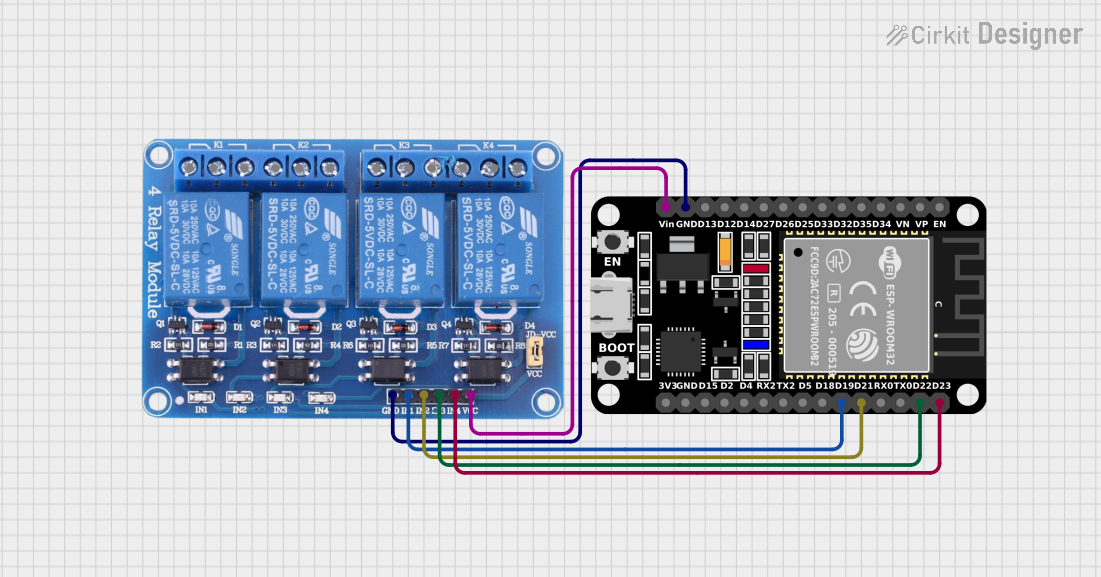
Example: Connecting to an Arduino UNO
Below is an example of how to control the 24V Single Channel Relay using an Arduino UNO:
Circuit Connections
- Connect the relay's VCC to a 24V DC power supply.
- Connect the relay's GND to the power supply ground.
- Connect the relay's IN pin to Arduino digital pin 7 (via a level shifter if needed for 24V logic).
- Connect the COM terminal to the load's power source.
- Connect the load to the NO terminal.
Arduino Code
// Define the relay control pin
const int relayPin = 7;

void setup() {
  pinMode(relayPin, OUTPUT); // Set the relay pin as an output
  digitalWrite(relayPin, LOW); // Ensure the relay is OFF at startup
}

void loop() {
  digitalWrite(relayPin, HIGH); // Turn the relay ON
  delay(5000); // Keep the relay ON for 5 seconds
  digitalWrite(relayPin, LOW); // Turn the relay OFF
  delay(5000); // Keep the relay OFF for 5 seconds
}
Note: If the Arduino operates at 5V logic, you may need a level shifter or transistor circuit to interface with the 24V relay.
Troubleshooting and FAQs
Common Issues and Solutions
Relay Not Switching
- Cause: Insufficient control signal voltage or current.
- Solution: Ensure the IN pin receives a 24V HIGH signal with sufficient current (~15-20 mA).
Load Not Turning ON/OFF
- Cause: Incorrect wiring of the load to the relay terminals.
- Solution: Verify the load is connected to the correct terminals (NO or NC) based on the desired behavior.
Relay Clicking but No Load Response
- Cause: Faulty or loose connections in the load circuit.
- Solution: Check all connections and ensure the load is functional.
Overheating
- Cause: Exceeding the relay's current rating.
- Solution: Use a relay with a higher current rating or reduce the load current.
FAQs
Q: Can I use this relay with a 5V microcontroller like Arduino?
A: Yes, but you will need a level shifter or a transistor circuit to step up the 5V control signal to 24V.
Q: Is the relay suitable for AC loads?
A: Yes, the relay can handle AC loads up to 250V, provided the current does not exceed 10A.
Q: Can I use this relay for inductive loads like motors?
A: Yes, but you should use a flyback diode across the load to protect the relay contacts from voltage spikes.
Q: What happens if I connect the load to both NO and NC terminals?
A: This is not recommended, as it may cause a short circuit or damage the relay. Only use one terminal at a time.